what about putting one inductor on the drain and another on the source of the mosfet?
output taken at source and drain of mosfet
if the 2 coils are bifilar wound on the same core, the opposite DC current cancel the flux
It is done on LAPS SLAPS for SLAM!
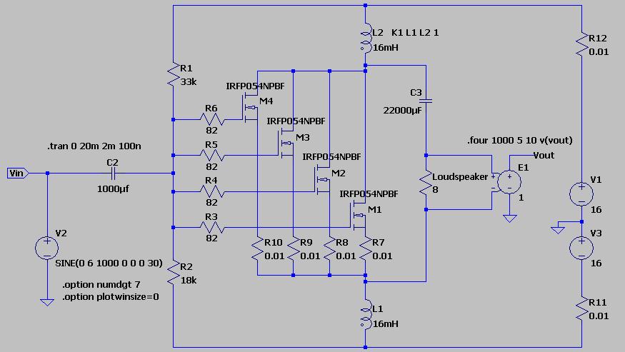
This circuit is not a follower because there is voltage amplification factor and the non linearity of mosfet are compensated by a feedback.
The low value of the choke is not compatble for a full range amplifier infact at low fequency the distortion is very high.
Coils could be 2 secondaries of psu transformer since the DC current Flux are canceling?
The coils are in series so the DC current Flux does not cancel. It will add.
You don't need to couple the coils, but there is free feed forward error correction to be had by coupling them tightly, so I can't imagine why one would not want that.
This circuit is not a follower because there is voltage amplification factor and the non linearity of mosfet are compensated by a feedback.
The feedback is more of a feed forward error correction. Not very different from Nelson Pass SuperSymmetry.
The low value of the choke is not compatble for a full range amplifier infact at low fequency the distortion is very high
His bifilar coil only had a few mH of inductance which is not enough for a good bass response.
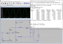
With 16 mH in each winding you get a very nice low distortion even at 10 Hz as in the simulation below.
2 x 100 meter of pvc-coated coupling wire was not enough in a aircore bifilar coil. Once he rewinded them on a steel core the distortion got back down to reasonable levels.
Once he got the coils up to 21 mH then he wrote this:
There was no significant difference between the SPL nor distortion from 20 Hz to 1000 Hz comparing the Trimodal with SLAPS
Attachments

Attachments
Thanks for the link Soundhappy!
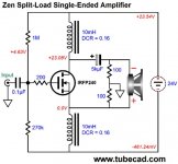
It is fun to read his article about using a split load phase splitter as an amp.
YouTube
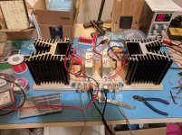
Here is my first test of this idea back in 2016. I was using a large air gapped transformer core. And I was wrong in the assumtion that it could run in class A/B. It was my large BIB that did not need many mW before being loud enough.
It is fun to read his article about using a split load phase splitter as an amp.
YouTube
Here is my first test of this idea back in 2016. I was using a large air gapped transformer core. And I was wrong in the assumtion that it could run in class A/B. It was my large BIB that did not need many mW before being loud enough.
Rather late to the party but I have rather a lot of time on my hands ")
I'm running the B1 Korg as preamp but will need a little lift for the MoFo. Reading back to post 1172.
Could I just pop 2x Edcor 600/15k in the case on the inputs of MoFo?
I'm running the B1 Korg as preamp but will need a little lift for the MoFo. Reading back to post 1172.
If i am right the B1 Korg has a voltage gain of about 6x and the Edcor 600/15k of 5x which makes for a substantial total of about 30x...
Much of the requirements depend on how much your source delivers.
Case A
I have a weak source that can deliver 0.56Vpp
I would want 12Vpp maximum at the entry of MOFO
Hence i need a voltage gain of 21.4x or appr. 27db
Case B
I have a second source that can deliver 2.8Vpp
In this case i only need a voltage gain of 4.2x or 13 db
(The B1 Korg alone would have enough gain but it cannot swing the required voltage, or at least not with reasonable distortion)
Consequently
for Case A i would use the complete B1 Korg to feed the Edcor
for Case B i would only use the buffer of the B1 Korg preamp
Could I just pop 2x Edcor 600/15k in the case on the inputs of MoFo?
Another build
One more for fugly!
And a question. While I was adjusting the bias, the current on my bench supply didn't match the expected voltage across the chokes. My chokes measured 0.9 ohms, aiming for 1.7A - that works out to 1.53V. When my supply was reading 1.7A, I was only seeing 1.2V. When I dialed it up to 1.5V the supply was showed 2A.
To calibrate things, I have a 0.5 ohm, 50W resistor, which my DMM measures accurately both hot and cold. Ramping up through 5V across it, my supply reads ~10% below expected current. That doesn't explain getting a higher than expected current in to the MoFo.
I measured the chokes (Hammond 159ZC) before soldering, and gave them a minute or so to settle.
My sinks can handle the extra heat, but I don't want to overload my power brick.
Any ideas what might be going on here?
Attachments
Fresh batteries - brilliant!
Now the chokes measure right at their spec'd 0.7 ohm, and, accounting for my supply's measured current error, the voltage is dead on.
I tried with a series resistor, but all I have is this 0.5 ohm which made too big of a dent in the numbers.
Thanks for the help, and thanks for the Mofo!!
Now the chokes measure right at their spec'd 0.7 ohm, and, accounting for my supply's measured current error, the voltage is dead on.
I tried with a series resistor, but all I have is this 0.5 ohm which made too big of a dent in the numbers.
Thanks for the help, and thanks for the Mofo!!

don't fret .......had same situation a week ago
whole chain of DVMs, while setting one Babelfish J2
suddenly Iq started to wander, tried measuring across 0R5 group, then across 0R34 group then across 0R235 group, without too much logic, wondering what's wrong... after few minutes realized that I'm ignoring Battery symbol on DMM screen
small details as these are easy to ignore, especially when being in state of suspense (normal when one is having limited mileage in particular area)
I was in state of suspense, even with milliooooon miles under the belt, simply because I was troubleshooting someone else's mess, so needing all 4 eyes wide open
- Home
- Amplifiers
- Pass Labs
- Build This MoFo!