Yup, probably a good idea.
Any mounting advice for a CPU cooler?
I was thinking of designing a custom PCB with a standard motherboard mount and use a standard intel back plate with the mosfet bent up flat against the PCB with cooler bolted on top?
Check out this post #1,368
Each channel is powered by 24V 5A Meanwell bricks
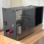
The mosfet is clamped to the cpu cooler copper pad using aluminum angle stock. The aluminum cpu cooler base was drilled for two M4 fasteners that secure the mosfet clamp.
The MoFo pcb has a couple holes drilled in strategic locations to line up with the cpu cooler mounting bosses for solid attachment so the stress of mounting was not solely on the mosfet legs.
CLC filter on separate psu feeding the PWM fan controller and fans.
Going down memory lane has me wanting to pair my new FE2022 preamp with Big MoFo 🤩.

I think I'm gonna have to get the old ms paint out to demonstrate the cooling technique I am thinking off (I am not a graphics guy) 🙄. As for PWM and DC control of the cooling fan. I was thinking of a DC control as this would amount to a simple voltage divider linear emitter follower (12V fan about 3.5W max at 300mA with 24V supply), but I am somewhat familiar with working with micro controllers, PWM would be best and could also provide other features such as a delayed relay start at the same time, something like the 8 Pin ATtiny85 (plus +5 regulated) would be great (I like through hole). As for separate PSU for fan supply I have found in admittedly 2 or 3 experiments, as long as careful consideration is paid to ground and nice big caps are present, noise isn't much off a problem, especially the back though a drop down voltage component.
Last edited:
Good luck with the fan and all that. It's a valid approach and it's been used for a myriad of applications with considerable success.
But nothing beats a fully passive, massive heatsink.
When I was servicing satellite transceivers and RF transmitters in the field (long time ago) the most common problem was fan failure and consequently dead transceivers / transmitters.
Only because most clients didn't want to invest in a more reliable solution. Which was going to be cheaper in the long run.
Your point of long term reliability is valid and understandable, but home audio is a different type of use case. A Noctua fan will probably last 5 lifetimes if used to cool a home audio amplifier, barring no user installation errors.
My biggest issue with CPU cooler/fan use is aesthetics. Mad Max looks aren’t WAF friendly 🤣.
My biggest issue with CPU cooler/fan use is aesthetics. Mad Max looks aren’t WAF friendly 🤣.
OK, I definitely don't want to shift the discussion to "active vs passive cooling pros and cons" one.
But home audio is an amp idling at 50 - 100mA per channel, class AB.
Here we have a Single Ended Class A Beast idling at 2A and dissipating 40 - 50W per a single Fet.
And yes, that fan can last 5 lifetimes and also can last only 5 minutes.
So everyone is free to decide what's the best way to deal with the issue.
In other news, the new UMS boards are on the way.
Any sight of them?
😗
I have them here. I just need to write them up. 🙂
I would be interested to hear what is that maximum power that you have your MoFo Mosfet dissipating.
For the last couple of months I have been close to 50W per device ( IRFP250s )
It's sounding very nice but this is the hottest I have every run O/P devices and I'm wondering if it's a bit too much.
thanks
For the last couple of months I have been close to 50W per device ( IRFP250s )
It's sounding very nice but this is the hottest I have every run O/P devices and I'm wondering if it's a bit too much.
thanks
IRFP250 have a 190W maximum dissipation at 25C with a 1.5W/C derating factor. Do the maths for your operating temperature and see if you're in the SOA..
https://www.vishay.com/docs/91212/irfp250.pdf
https://www.vishay.com/docs/91212/irfp250.pdf
Pass DIY Addict
Joined 2000
Paid Member
Depending on your configuration, you may be able to skip the silpad and go directly with the mosfet directly on the sink with some thermal paste. WARNING: doing so will make your sinks live (positive voltage imparted by the mosfet) and this can ONLY be done if each device is mounted on its own sink and the sinks for each channel are 1) independent of one another and 2) not grounded (which is typically viewed as poor form).
But, if you are looking for maximum dissipation from your device, this will get you more power with better cooling.
My example of this is here: https://www.diyaudio.com/community/threads/build-this-mofo.313649/post-5599877
But, if you are looking for maximum dissipation from your device, this will get you more power with better cooling.
My example of this is here: https://www.diyaudio.com/community/threads/build-this-mofo.313649/post-5599877
For those using IRFP250 mosfets in their MoFo, I am curious to know if anyone has tried using a source degeneration resistor and if anyone has tried this I would be interested to know what value degen resistor you used and to hear your subjective impressions of the differences they made.
I am considering trying 0.05 - 0.1R degen resistors.
thanks
I am considering trying 0.05 - 0.1R degen resistors.
thanks
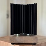
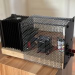
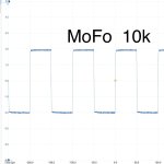
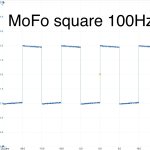
Thank you, Michael, for a very learning and enjoyable building project and thanks to all contributors. I made mine to a tribute to the original design, plus a cat fence. They sounded better than I hoped, really nice. My PC oscilloscope can’t measure better than 0.15% and have a lot of inbound noise but got some decent square waves, without load. I hope to battle my way through REW settings and get some nice loaded fft’s but haven’t succeeded yet. The sound is not as precise compared to other followers but laid back, not offensive and enjoyable. You can have really short speaker cables with mono blocks. 🙂
I messed up one pcb at output. I had to reroute. Is new pcb prepared for cables or screw socket?
How much gain can 193T handle, papers say 2A? I have biased them to 1A75. Heat sink is moderate warm after hours. Maybe a step up in inductor … hmm.
Pre: Turtle Iron Pumpkin strapped at 6 dB gain
Alt pre: FE2022 gain ~7 dB as gain stage
Speaker: medium size 95 dB, 38 - 22k Hz
Attachments

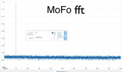
nicely done sov! how are you powering it? I'm looking into building one myself. Have you checked out Arta for FFT? its free and easy to use (https://artalabs.hr/)
- Home
- Amplifiers
- Pass Labs
- Build This MoFo!