
I think you can raise the power supply to 28-30Vdc for the most of it into 8ohm loads which will bring at least 40wrms, this with ~3A bias.
The mosfet works better at higher voltages, more linear and with even lower output impedance.
The mosfet works better at higher voltages, more linear and with even lower output impedance.
Nice! Super fun!
In other news, the new UMS boards are on the way.
My puck version is up last in the four-part trilogy. 🙂
In other news, the new UMS boards are on the way.
My puck version is up last in the four-part trilogy. 🙂
Mike, I love the original MoFo and can't wait to see what you have cooked up. 
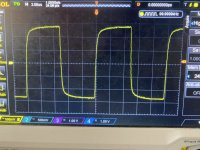
Today I received a signal generator and since the puck Mofo was playing in the system I used one channel as DUT.
First I ran some square waves then some sines.
With sines it does 2hz-1.6Mhz at -3db rolloff at both ends and is close to flat from 10hz-160khz.
Measured with 8ohms load.
First I ran some square waves then some sines.
With sines it does 2hz-1.6Mhz at -3db rolloff at both ends and is close to flat from 10hz-160khz.
Measured with 8ohms load.
Attachments
Pass DIY Addict
Joined 2000
Paid Member
I did something similar years ago and remember be fantastically impressed with the bandwidth of this power buffer! I think it measured essentially flat out to 300kHz.
I am waiting for the pcb for a buffered version and will repeat the test out of curiosity 😁
100khz+ bandwidth and reduced distortion as the frequency increases makes this design very nice.
It sounds awesome too.
100khz+ bandwidth and reduced distortion as the frequency increases makes this design very nice.
It sounds awesome too.
Good morning, gentlemen.
What voltage and power for the mosfet protection zener?
Thank you in advance for your answers
What voltage and power for the mosfet protection zener?
Thank you in advance for your answers
Pass DIY Addict
Joined 2000
Paid Member
A 20v 5w part should do it. Maybe something like this (1N5357). I added a 1000uF cap to the DC input of the amp and it also prevents the sudden collapse of the coil well enough to protect the output mosfet.
I'm thinking of building a MoFo, it looks very interesting but I'm wondering about a few things.
How is thermal stability/bias drift?
Could a 'auto bias' circuit be a good idea? like:

Also M1 is dissipating a lot of constant heat (50w) would a CPU cooler be a good to cool this beast?
I have 24V 6A power bricks already, and am looking to making this (at least the prototype) nice and cheap.
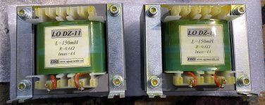
Would a Hammond 159ZC at 60mH, 2A, 700mOhm (Digikey 159ZC) or a
Signal Transformer CH-4 at 70mH, 4A, 600mOhm (Digikey CH-4) be a good fit?
How much standing current could I take this up-to?
How is thermal stability/bias drift?
Could a 'auto bias' circuit be a good idea? like:
Also M1 is dissipating a lot of constant heat (50w) would a CPU cooler be a good to cool this beast?
I have 24V 6A power bricks already, and am looking to making this (at least the prototype) nice and cheap.
Would a Hammond 159ZC at 60mH, 2A, 700mOhm (Digikey 159ZC) or a
Signal Transformer CH-4 at 70mH, 4A, 600mOhm (Digikey CH-4) be a good fit?
How much standing current could I take this up-to?
Last edited:
I built a MoFo like the original cct sans the zeners that idles at 2A.
The bias is very stable, does not fluctuate at all.
The beauty of Mr. MR's cct s it allows you to vary the bias if you want depending on your hardware requirements - sinks, choke, etc.
You will not have that flexibility with your idea.
Also I think IRFP240 is not that great in that position. Try something with more Gm, like 140, 150, 250. You can also try a puck, that will dissipate a lot of heat.
Well if the bias is stable then better just to stick with a pot. I'm wondering would a capacitor between the wiper of the pot (P1) and ground be better to reduce power supply noise?
I have IRFP140's but I'd be concerned with the longevity of such a single TO-247 device.
By puck I presume its something like:

An IXYS IXFN73N30 is less than £10.
Looking way back at post #507 @Ralph G seems to have had good look with a IXFK44N50 and the Hammond 159ZC choke.
So either a puck style or 2x IRFP140's.. hmmmmm 🤔
I have IRFP140's but I'd be concerned with the longevity of such a single TO-247 device.
By puck I presume its something like:
An IXYS IXFN73N30 is less than £10.
Looking way back at post #507 @Ralph G seems to have had good look with a IXFK44N50 and the Hammond 159ZC choke.
So either a puck style or 2x IRFP140's.. hmmmmm 🤔
I use irfp150 in my MoFo at 2A.
Attached to a massive heatsink.
I also drop the PSU voltage to 22V through a CapMx, then couple more volts across the choke (MOT).
So 20V across the fet@2A is 40W.
The get seems not to mind it, has been running like that for 4-5 years now.
I wouldn't parallel 2 gets as then you'll need careful matching and source resistors. Kind of goes against the beauty of simplicity.
But it's up to you to experiment.
Yup, probably a good idea.
Any mounting advice for a CPU cooler?
I was thinking of designing a custom PCB with a standard motherboard mount and use a standard intel back plate with the mosfet bent up flat against the PCB with cooler bolted on top?
Any mounting advice for a CPU cooler?
I was thinking of designing a custom PCB with a standard motherboard mount and use a standard intel back plate with the mosfet bent up flat against the PCB with cooler bolted on top?
Last edited:
- Home
- Amplifiers
- Pass Labs
- Build This MoFo!