A power mosfet in that position seems very much out of place, IMHO. Why not use a jfet, if a fet must be used? But a bipolar seems just fine as long as it doesn't oscillate.
This is off course just a suggestion, and I used this particular power MOSFET because I had a model for it. But off course, a small TO92 MOSFET such as ZVP2206/2210/3306/3310 will do just as well. The critical point is that whatever is in this position MUST have it's gate/base some 2 - 3 volts below V_OUT to give sufficient headroom for the CCS next to it. So either a BJT AND a LED underneath, or just a MOSFET with high enough VGS.
Btw., I got the idea from the Passlabs Alephono RIAA amp, it uses a mosfet - same IRF9610 btw. - in a similar position, after the differential input stage. Or look at the schematics of the Borbely shunt regulator, he basically does the same, but with a small TO92 MOSFET.
It is also about 20dB better, but with reduced bandwidth. I tried it without the compensation cap and it was still stable.
The MOSFET is about optimal in this position, imho.. Bandwidth could be improved by a cascode (again, same as in alephono), then it is a few dB better at higher frequencies, but this would mean one more bjt and 2 more resistors, and I am not sure if it is needed.
Without the compensation cap I see the phase of V_OUT crossing 360° beyond 10-30 MHz, this might indicate potential problems (my prototype oscillated exactly at such a crossing point).
Martin,
Could you try feeding the Zener directly from the +ve rail with a seperate resistor (or perhaps a BF245 as CCS) and connect the R78, diode string to ground - this was mentioned awhile ago and it would be good to see the result in this new configuration..
Looking good.
Could you try feeding the Zener directly from the +ve rail with a seperate resistor (or perhaps a BF245 as CCS) and connect the R78, diode string to ground - this was mentioned awhile ago and it would be good to see the result in this new configuration..
Looking good.
James,
I can connect R78 directly to ground but do not see any difference, now R78 is not adding much current anymore, so either way should be fine.
About your second question, do you mean just adding more current by an additional resistor to V+ or actually removing the Zener from the emitter of Q36? The latter cannot be done with the current configuration, though I did try an alternative where I buffered the Zener with a (PNP) BJT - directly connected to Q36 emitter-emitter - in order to introduce an RC filter. That creates a differential amp at this position (unless Q36 is not also called a diff amp?).
By a direct feed from the rail (resistor should be adequate) you can adjust the current thru the zener and pick the "sweet spot" and also avoid adding any zener noise thru the "string" - should be quite useful for different voltages. I also thought an RC network would be useful there but it seems to produce problems instead - sounded a bit "rough/edge", but this was with the previous input CCS circuit, so maybe the effect isn't connected with this cct.
ikoflexer said:A power mosfet in that position seems very much out of place, IMHO. Why not use a jfet, if a fet must be used? But a bipolar seems just fine as long as it doesn't oscillate.
Jim, I would be surprised if the regulator worked just fine at those kind of currents; my simulations show some very erratic behaviour; I am using the alternate solver, which supposedly is much more accurate. I am curious about the values you used in your schematic. Any chance you could post that? A bit of off-topic here, UW is my alma mater, loved that area.
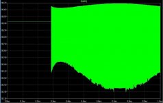
I agree that I am pushing this well past the guidelines. I am looking for a regulator for a headphone amp I am planning to build and it seemed like a good idea to see if this one would work for it with a transformer I already own. I just checked it with more sensible currents and voltages. The simulation still shows oscillation. Here is my original test with the result of the Transient Analysis. This circuit should match the one in post 446 with my voltage and current requirements.
Edit: Small world, I'm a Biology tech at UW.
Attachments
I can confirm that the mosfet driver version oscillates too. The cap on its gate doesn't do away with the oscillation, just makes it small in magnitude. It shows under some magnification. Oscillation does not seem dependent on the current magnitude of the load (Jim pointed this out too).
ikoflexer said:I can confirm that the mosfet driver version oscillates too. The cap on its gate doesn't do away with the oscillation, just makes it small in magnitude. It shows under some magnification. Oscillation does not seem dependent on the current magnitude of the load (Jim pointed this out too).
Thanks for checking this. I tried this again. All I can see is a trace of the 1000 Hz component I put into the load. I can not see any oscillation. Please check the frequency of this signal on your output. It may be some difference in our spice models of components.
Thanks
Jim
I did not see any oscillation in the recent versions but that does not mean that there aren't any. The only proof is building it, all versions are simple enough to be implemented on a singlesided PCB. I might try the most recent one but will need at least a week or so.
When my original prototype oscillated I later saw that the phase of the output signal was going beyond 360°, which I think is one hint for oscillation. I had put a small inductance in place of R8 in an attempt to compensate the circuit, but in fact it was oscillating lik hell at 10MHz. Removing the inductance killed the oscillations and the phase went also back to below 360° in simulation.
Including the compensation cap in the recent versions prevents the phase from going to beyond 360 at high frequencies (some 10s of MHz). Btw., I put in 6nH series inductance into the cap models (ballpark figure for low ESL types) which might also help.
JimT said:
I agree that I am pushing this well past the guidelines. I am looking for a regulator for a headphone amp I am planning to build and it seemed like a good idea to see if this one would work for it with a transformer I already own. I just checked it with more sensible currents and voltages. The simulation still shows oscillation. Here is my original test with the result of the Transient Analysis. This circuit should match the one in post 446 with my voltage and current requirements.
Edit: Small world, I'm a Biology tech at UW.
Put a 0.5 to 1 ohms in series with your Co2 output cap. That makes it more real-live and will cut your oscillations if not kill it completely.
Jan Didden
Thanks Jan,
It's not shown on the schematic, but all the capacitors did have some series resistance in their models. I tried a version with a resistor inline with my output cap (C02) and reran the test. I tried a lot of values between .1 and 10 ohms, but all showed oscillation in the simulation. I tried this in versions with the LED type CCS and the Pass style mosfet CCS. Both oscillated on the outputs. It may be that this circuit is fine in reality, but perhaps a space for something like the compensation capacitor should be added to the PCB. I have to admit that I am really out of my depth here, just some idiot playing with a laptop.
Thanks
Jim
JimT said:Thanks Jan,
It's not shown on the schematic, but all the capacitors did have some series resistance in their models. I tried a version with a resistor inline with my output cap (C02) and reran the test. I tried a lot of values between .1 and 10 ohms, but all showed oscillation in the simulation. I tried this in versions with the LED type CCS and the Pass style mosfet CCS. Both oscillated on the outputs. It may be that this circuit is fine in reality, but perhaps a space for something like the compensation capacitor should be added to the PCB. I have to admit that I am really out of my depth here, just some idiot playing with a laptop.
Thanks
Jim
No, you make a lot of sense. I don't have the time ATM to get involved more deeply here, maybe Martin has some ideas.
But don't forget that we/you guys had a perfectly good design that someone was going to build and test. There's always scope for improvements (real or perceived) and other options and other parts etc etc ad infinitum. But in engineering, at some point you need to say: this is my design, now I'm gonna build it.
I thought you were at that point...
Jan Didden
I agree with Jan on this one. Perhaps the version just before the alternate ccs should be named "something" beta and built; or just tested, didn't Martin build that one already? I am a bit too busy with the high voltage one right now, unfortunately, or I'd do it myself.
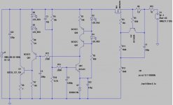
Perhaps the version we thought was stable should be once more checked. The attached image, which was discussed a bit earlier, before the alternative ccs, also oscillates in simulation. Perhaps someone can double check in case I made a mistake somewhere.
Attachments
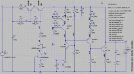
Don't use CFP especially hybrid(bjt+mosfet) as shunt element with global NFB,because they prone to oscillate and always need compensation cap in real world. In case CFP to improve/get stability "master " part of CFP should run on high current to get high Ft -higher then "slave"- it's impossible with mosfet in this position in case voltage regulator.
IMHO we don't need output impedance in range microohms(in real world remote sensing and extremal wise layout required to this)so we don't need CFP here...several miliohms will be ok
Do You play with topolgy from POOGE reg?(example in attached image).
In BJT version to get headroom for CCS (error amp load) smart idea is cut trace in point "A" and supply CCS (error amp load) from inpedent voltage regulator (for example zener follower+gyrator).
Attachments
ikoflexer said:Perhaps the version we thought was stable should be once more checked. The attached image, which was discussed a bit earlier, before the alternative ccs, also oscillates in simulation. Perhaps someone can double check in case I made a mistake somewhere.
Play with R8...
Jan Didden
The attached image, which was discussed a bit earlier, before the alternative ccs, also oscillates in simulation.
This is exactly the version that I built, except that C3 was 470µF instead of 1 µF (do a noise analysis and you will see why). I initially had a 3.3 µH inductance instead of a resistance for R8 and it did oscillate happily at 10 MHz, as I explained before. Perhaps you make this change in your simulation to see how that reacts (and watch the phase of the output signal).
However, putting in a 5.8 Ohm resistor for R8 stopped the oscillation and my prototype was stable. And when I simulated it I did no longer see any indication for oscillation. Note that if you test for transient response at a high enough frequency you can off course "upset" the regulator, maybe this is what you are seing as oscillation?
I was about to clean up my layout a little bit and built a second prototype but then someone complained that the current source portion would not work properly, and that is how the new versions came about. I do not think that there is an issue with either the new (primary) current source, or the old one, with the exception that the new version is simpler and more scalable.
One last comment: I do get different results with different BJT and Mosfet versions. For instance, I have a normal model and a subcircuit for IRF9610 and they behave differently.
There has been a lot of input and testing lately from many of you guy with lots of interesting and feasible approaches but as someone said the simple basic topology has its limits too so we need to focus on one approach as Jan has suggested.
I see Martin has really explore many avenues on both the CCS and shunt portion and appears to have arrived to some solid conclusions and I also happen to like the new simpler CCS which also is more scalable as mentioned.
Well I have given my humble opinion but we need others too in order to move ahead and finally get the GB going again if there are no further concerns here.
So please vent your opinions….
Cheers
Uchi Deshi said:Don't use CFP especially hybrid(bjt+mosfet)
do you mean small bjt & big mosfet ?
I use small mosfet & big BJT with out a problem in real life so long as they are placed very close to each other.
mike
- Status
- Not open for further replies.
- Home
- Amplifiers
- Solid State
- Bipolar discrete shunt regulators