The base currents of the two lowish gain BJTs destroys the constant voltage across the first LED. Varying the LED current/voltage directly changes the voltage across the first resistor.
The current source is not optimal for higher currents, no doubt about that, and we should investigate alternatives, like the one ikoflexer proposed, or other VBE multiplier types. Having said that:
1. You need to state your current requirements to make a useful assumption about what CCS to use.
2. The "lowish" (current) gain does not show up in simulation, at least when calculating PSRR. Replacing BD140-160 with other transistors, e.g. BC327-40, etc., did not show any noteworthy improvement in PSRR (transient response may be another matter). Note also that the base is held at a fixed voltage due to the low dynamic impedance of the LEDs (6 Ohms or so at 10mA), so you need to calculate the impedance looking into the base of Q5 and Q6 in order to make an assessment of the stability of this CCS.
3. The regulator seems to be limited in terms of noise performance, see the chapter in the article I referenced a few posts earlier, this should apply to the current topology as well. So first of all, we need a big bypass cap on the voltage reference to shunt it's noise and even then we may not get optimal results. The question now is: how far do we want to go with this current design?
Hi,
could a tl431 replace the first LED, 2.5V here would not be too big a problem in terms of drop out voltage. A cap, again to reduce noise.
The "only" problem that I can't solve is the non constant voltage across that first resistor. All the rest of this shunt reg seems to be very good.
Can we find a simple and cheap and low PCB area solution that sounds as good as this is reputed to be?
I just ran an impedance @ DC on the first CCS using ~60mA of current to the load. The effective Z of the CCS was only 700r!
Andrew has a valid concern. I don't know how much it shows up in measurements, but the issue is there.
OTOH, people probably don't want to throw away all the work done so far. So, the simplest chnage I can think of is use darlingtons for the two input transistors. With some luck, no changes to the PCB are necessary.
For example, BD675/676 series, Hfe min 750, same pin-out; but there are others.
Jan Didden
that gets the LED current up to ~ 95% of the FET CCS
will darlington/s sound as good as single BJTs?
Aren't they a lot slower? That was what was nice about the BD139/140.
will darlington/s sound as good as single BJTs?
Aren't they a lot slower? That was what was nice about the BD139/140.
AndrewT said:that gets the LED current up to ~ 95% of the FET CCS
will darlington/s sound as good as single BJTs?
Aren't they a lot slower? That was what was nice about the BD139/140.
I didn't really search for replacement darlingtons, but yes we should use types with at least similar Ft's as those BD's.
Jan Didden
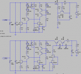
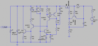
I still think that you are barking up the wrong tree but let's not quibble. Here is an alternative version, VBE mulitplier with a FET, IRFP9610 in this case. This is VERY scalable in terms of current draw, and several amperes (at maybe reduced performance?) should be feasible. BTW, the same type used in the original ZEN amp and it is similar to what Erno Borbely is using in his new shuntreg, except for the different capacitor connection:
Attachments
Martin, I also got some very nice simulation results with this circuit. Just as good Zout as the original circuit (in fact a little better). I think in this application the irf9610 does nicely compared to the irfp9240 because of its lower capacitance.
Question: what would your choice be for a shunt bjt capable of operating at 250V-300V, while shunting about 200mA? I guess I'm looking for a high voltage high current NPN but don't have much experience with such animals.
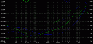
deletes 4semiconductors and adds two resistor. That meets cheap and simple and economic on PCB area.MRupp said:Here is what my simulator shows in terms of PSRR, both look pretty similar in performance. Blue is the original LED current source and green is the new one:
Heck, it even performs.
I don't like all those steeper slopes in the 9610 version. Does it need some compensation?
Yes looks good indeed. Probably needs some more headroom and therefore some more dissipation, but that should be acceptable.
Jan Didden
Jan Didden
MRupp said:I still think that you are barking up the wrong tree but let's not quibble. Here is an alternative version, VBE mulitplier with a FET, IRFP9610 in this case. This is VERY scalable in terms of current draw, and several amperes (at maybe reduced performance?) should be feasible. BTW, the same type used in the original ZEN amp and it is similar to what Erno Borbely is using in his new shuntreg, except for the different capacitor connection:
Looks really nice Martin and yes is like the original Zen and F2 type CCS, excellent work.
😎
PS: I guess it can also be done with a N type trany a la ZV4? We might get a better response with a IRF610
I don't like all those steeper slopes in the 9610 version. Does it need some compensation?
The first steep phase slope / trough is introduced by the RCR network. Putting the JFET current source back in to bias Q22 eliminates it. I am not sure if it will cause an issue, my first guess would be that it doesn't. And I tried compensation, same as in the Pass CCS, and it did not compensate anything, not as far as I could see. Off course we could leave in some space for a small cap, just in case.
deletes 4semiconductors and adds two resistor. That meets cheap and simple and economic on PCB area.
If that is your objective you might like this version, with the second CCS (2 LEDs) replaced by another bootstrapped VBE multiplier. A further benefit is that it needs less voltage accross it, which comes in handy if you need a 6 Volt or maybe even a 5 Volt version of the regulator - with a LED as voltage reference. And we can eliminate another LED that we needed for Q1 (Q29 in this schematic). PSRR is identical but load regulation is even slightly better - in simulation:
Attachments
PS: I guess it can also be done with a N type trany a la ZV4? We might get a better response with a IRF610
Hmmm, I did not consider this, if I do get some more time I might try, but maybe someone else would be quicker? Obviously, if we need supplies for both polarities we will reintroduce the P channel (?). Another word of caution, these are simulations and I think I read that MOSFET models are "less than perfect" to put it mildly. Also, the CCS may not be the dominant element in terms of overall performance.
MRupp said:
Obviously, if we need supplies for both polarities we will reintroduce the P channel (?).
Also, the CCS may not be the dominant element in terms of overall performance.
Good question... if better we might keep the N type for both polarities.
Yes... something to consider too...
Tony,
at first glance it would require more headroom. The current version is "biased to ground" - if that is the right description, so you easily get the 4 Volts VGS but you may need less than 4 Volts VDS so that you get away with less headroom. The N version takes its bias from the positive supply, so you need some extra volts to bias the BJT. Just what I could make out at this time of the evening.
at first glance it would require more headroom. The current version is "biased to ground" - if that is the right description, so you easily get the 4 Volts VGS but you may need less than 4 Volts VDS so that you get away with less headroom. The N version takes its bias from the positive supply, so you need some extra volts to bias the BJT. Just what I could make out at this time of the evening.
MRupp said:I still think that you are barking up the wrong tree but let's not quibble. Here is an alternative version, VBE mulitplier with a FET, IRFP9610 in this case. This is VERY scalable in terms of current draw, and several amperes (at maybe reduced performance?) should be feasible. BTW, the same type used in the original ZEN amp and it is similar to what Erno Borbely is using in his new shuntreg, except for the different capacitor connection:
I was testing this version in LTSpice and get oscillation. A 200p capacitor to ground off the base of Q15 ( the BC557 that connects to the BD139) controls this. I used the directive ".tran 0 60ms 0 .1u" to look at transients and this is where the oscillation shows up. Perhaps my problem was that I was stressing the regulator too much. I put 400ma through the CCS. The load was 286ma with a 1000Hz 50ma component. I have tried most of the different types of CCS's and get this oscillation with them all, so I suspect it's either my method or the shunt.
Thanks
Jim
Thanks Jim,
I have not yet tried any transient response commands but adding the cap as you mentioned seems to be a good idea, I assume you mean base to collector of level shifter Q15 (Q1) ?
I was previously referring to an additional compensation cap in the main current source, same as in the ZEN current source, and there I did not see any improvement, event though there still might be a reason for it that I do not see.
And for discussion, I have another modification, as an alternative to the previous version: Q1 (Q15 / Q29) is replaced by a MOSFET as level shifter, this gets rid of the remaining LED and resistor. TO92 types like ZVPxxyy, BS250, etc. would be good candidates even though the schematics shows IRF9610 (VGS should be 2-3 Volts at least) - and I have included a compensation 220pF cap as stated above:
Attachments
This is stable in my simulation. It is also about 20dB better, but with reduced bandwidth. I tried it without the compensation cap and it was still stable. This should be looked into.
Thanks
Jim
Thanks
Jim
A power mosfet in that position seems very much out of place, IMHO. Why not use a jfet, if a fet must be used? But a bipolar seems just fine as long as it doesn't oscillate.
Jim, I would be surprised if the regulator worked just fine at those kind of currents; my simulations show some very erratic behaviour; I am using the alternate solver, which supposedly is much more accurate. I am curious about the values you used in your schematic. Any chance you could post that? A bit of off-topic here, UW is my alma mater, loved that area.
Jim, I would be surprised if the regulator worked just fine at those kind of currents; my simulations show some very erratic behaviour; I am using the alternate solver, which supposedly is much more accurate. I am curious about the values you used in your schematic. Any chance you could post that? A bit of off-topic here, UW is my alma mater, loved that area.
- Status
- Not open for further replies.
- Home
- Amplifiers
- Solid State
- Bipolar discrete shunt regulators


