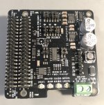
I am sorry, but what I can see right over the copper shield is the FiFioPi...
If there was an IsolatorPi we would see its power connector on the right-hand side, just below the 3,3V connector of FiFoPi.
Maybe you can make a better picture from a side such that we can understand how this is mounted?
If there was an IsolatorPi we would see its power connector on the right-hand side, just below the 3,3V connector of FiFoPi.
Maybe you can make a better picture from a side such that we can understand how this is mounted?

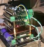
sorry about the picture. this is the picture with isolatorPi ll fitted.I am sorry, but what I can see right over the copper shield is the FiFioPi...
If there was an IsolatorPi we would see its power connector on the right-hand side, just below the 3,3V connector of FiFoPi.
Maybe you can make a better picture from a side such that we can understand how this is mounted?
Attachments
Thanks. Now it seems about right. Can you connect MonitorPi Pro just for a moment from the secondary stack to the FifoPi Q7 on the first stack. Just to double-check the problem is with FiFoPi not getting the signal.
Can you also try disconnecting the DSD Mute cable (yellow and blue) for a moment, and test. I did not have this cable connected.
Can you also try disconnecting the DSD Mute cable (yellow and blue) for a moment, and test. I did not have this cable connected.
Hello,
If i am right that uc board with caps needs a considerable current to be charged and i don't know any shunt supply that can do this.
Maybe a Tent shunt right on the board where it is needed ( so the signal board) could work?
The Tent has a lower output impedance than the contact resistance introduced by the green connector. It has reduced current capabilities so that should be checked.
But we got confirmed that this shunt works perfectly for the dac board.
Someone should try. I will use 5 volt Tent for dirty side Fifopi. There are possibly more areas where they can be used ( my friend uses them for the input stage of his Hiraga power amp)
Greetings Eduard
That is definitely something to consider regarding the charge current.Hello,
If i am right that uc board with caps needs a considerable current to be charged and i don't know any shunt supply that can do this.
Maybe a Tent shunt right on the board where it is needed ( so the signal board) could work?
The Tent has a lower output impedance than the contact resistance introduced by the green connector. It has reduced current capabilities so that should be checked.
But we got confirmed that this shunt works perfectly for the dac board.
Someone should try. I will use 5 volt Tent for dirty side Fifopi. There are possibly more areas where they can be used ( my friend uses them for the input stage of his Hiraga power amp)
Greetings Eduard
I was looking to power the dirty side of Q7 with a Salas Ultrabib 1.3 but not sure if I would gain anything rather than just using a LinearPi + UcCond. to power both the Rpi and dirty side. What do you think Eduard
Ian made this note in the UcCond. manual, but 100mA of current from a shunt regulator might simply be to low:
“ The internal charging current limitation is 1A. If the power supply it will attach to has output current less than that, it
may take longer time to charge the UcConditioner to 5V if it is fully empty. In this case, I would suggest pre-charge
the UcConditioner with a 5V USB power adapter at the first time of use. Both the UC FULL LED and
CONDITIONING LED will light up when UcConditioner is full.”
The Salas ultrabib can deliver much more, but off course with a lot of heat sink.
I get no signal from isolatorPi ll when I use HDMipi MKll transmitter to DDC stack, I want to try isolatorpi ll in Master mode. There is a very good sound with no isolator Pi ll.Thanks. Now it seems about right. Can you connect MonitorPi Pro just for a moment from the secondary stack to the FifoPi Q7 on the first stack. Just to double-check the problem is with FiFoPi not getting the signal.
Can you also try disconnecting the DSD Mute cable (yellow and blue) for a moment, and test. I did not have this cable connected.
Hello Miklau,
I have some uc boards too so i can kind of studied the manuals. Pretty sure that a shunt would not be the right way to charge the big caps. If it has to charge the caps with the current limited to 1 A it will still be a lot for an average shunt supply.
I will not be even using uc conditioner for the five volt but probably a rather simple LC or LCRC prefiltering. As a German member has noticed having a shunt board close to the consumer did improve things in his dac.
If i am right a power supply would optimally filter things in two directions ( like a filter positioned at the primary side of your transformer) so introducing a kind of barrier between the dirty side of the fifopi and the rest of your gear could be a plus.
If you tell me it probably won't matter why still spend hundreds of $ on clocks.
If the old Philips engineers who started with CD would not be close to dementia they should read this thread and be surprised.
Greetings Eduard


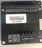
@geiren I checked my configuration of IsolatorPI MKIi and I run it with different settings than yours. My isolator is set to SLAVE clock mode and your was set to MASTER clock mode. That is probably why it was not working on your side. Check J12 and J13 on mine below:
You could also consider skipping HDMipi MKll transmitter and getting the I2S signal from the first stack to the second stack via GPIO. This is what I have done - removed the HDMI transmitter from the first stack and the DDC from the second stack. The stack are connected over GPIO.
I am waiting for #21B GPIO input adapter for FifoPi to connect it to the second stack. Then will connect FifoPi from stack one over the u.fl wires to the GPIO input adapter on the second stack. This will be better than double I2S/HDMI + HDMI/I2S conversions!
Eventually, I intend to install DDC on the first stack, so I keep additional input options.
Attachments
@Spacejack. isolatorPill does not work in slave clock mode either. I will look at your new setup and buy a new card and try. thanks for all the help
just out of curiosity, what is the input voltage you give to the isolator II in your setup?@geiren I checked my configuration of IsolatorPI MKIi and I run it with different settings than yours. My isolator is set to SLAVE clock mode and your was set to MASTER clock mode. That is probably why it was not working on your side. Check J12 and J13 on mine below:
You could also consider skipping HDMipi MKll transmitter and getting the I2S signal from the first stack to the second stack via GPIO. This is what I have done - removed the HDMI transmitter from the first stack and the DDC from the second stack. The stack are connected over GPIO.
I am waiting for #21B GPIO input adapter for FifoPi to connect it to the second stack. Then will connect FifoPi from stack one over the u.fl wires to the GPIO input adapter on the second stack. This will be better than double I2S/HDMI + HDMI/I2S conversions!
Eventually, I intend to install DDC on the first stack, so I keep additional input options.
I need a little bit off help with my 2 pcs. lifepo4 mini, they will not go in to pure mode(D10), even if full led (D7) is on. I can trig pure mode with a power off/on, they are fed with seperate 6vac/5a.
any god an idea? @iancanada?
any god an idea? @iancanada?
Last edited:
Have been very busy. Here are a new update.
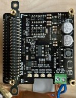
UcConditioner Pro 5V

UcConditioner Pro 5V
- Ultracapacitors are pre-installed. Plug and play. No need for any soldering job.
- Ultra-low ESR, 70% lower than the previous versions
- New high efficiency management chip to reduce the peak charging current, speed up the charging time and make the overall EMI noise even lower
- Optimized PCB layout for better performance
- Equipped with vertical mounting brackets
What frequency clock should I get if I listen mainly to cd quality flac? I want to update my fifopi7mk2 clocks. First with the one that handles redbook flacs. I can always get the other one later right?
- Home
- Source & Line
- Digital Line Level
- Asynchronous I2S FIFO project, an ultimate weapon to fight the jitter