Hello,
Google is your friend.
https://www.tentlabs.com/Components/Shuntcomp/index.html
By the way he is also involved in the Grimm products.
For the Fifopi i asked him if he could make one with a bit higher mA than the standard one which is 80 mA and i got 100mA which is about the max for his board without a new engineering process. If i am right the current being taken is 130 mA so once you are getting to close it will not function properly but i asked Ian about the needed current
and Guido also assured me his unit will be more than enough.
As you can see they are a piece of cake to install and very cost effective.
Greetings Eduard
Last edited:
It’s sharing a home made simple 7vdc psu. 5,5 vac in, 4 schottky diodes, 2 x 3600uf and 2 100nf. Gives approx. 7vdc out to shunt reg.@Lso What is the powersupply before Tenlabs? Are they all connected to the same powersupply or separate lines?

Hello,
With the DDDAC board that also use a shunt made by Guido Tent. The board has a 7810 as a preregulator.
Some people removed the 7810 and used a passive CLC supply. Fewer people used a choke input at this stage. However you must take care you are not to much above 10 volt to prevent overheating.
I am planning to do choke input as well.
Probably making this part with a small footprint will be an advantage too.
Greetings, Eduard
Hello LSO,
You can change the CRC network in the shunt application notes into CLC by simple replacing the resistor by a choke.
The shunt takes a constant current from that network of 130 mA so you need a 150 mA rated choke. Something like a Lundahl ll1673 which is 5 Henry 200 mA and 15 ohm dcr. 15×130 mA is nearly 2 volt voltage drop.
They are not the cheapest chokes and you will need two because you are a using a positive and a negative shunt?
Making it a choke input will certainly require another transformer.
A few months ago there were some Lundahls available here on swapmeet in Belgium. If you want to save some money they can be used too.
Greetings,Eduard
Just adding… while assuming you’re not adding chokes for every dac Channel…. one DAC module (2 channels) draws like 250mA, so for one DAC board your choke must be able to take like 300mA. For every deck more you need to multiply that.
to keep things on a steady 10 volts, I would rather suggest, assuming you are using a dddac power supply, to add the choke between the two filter capacitors in place of the 0,1 Ohm resistor (CLC) and trim the power supply to 10,5 volts (you loose 0,5V at the DAC module input) - connect this to the 12 volt input of the Mainboard and remove the 7810….
everything else will give varying voltages round 10 volt. If you know what you are doing you can tweak this, but sometimes mains voltages vary also a lot. Hence I like rather regulated voltage levels
Hello Doede,
He added the Tent shunts to a more basic Canadian dac after i suggested him that installing the power where it should be would be a safe bet
I just mentioned " our DDDAC" to show that there could be some more tricks. I mean some people started using them already a few years ago.
Greetings Eduard
He added the Tent shunts to a more basic Canadian dac after i suggested him that installing the power where it should be would be a safe bet
I just mentioned " our DDDAC" to show that there could be some more tricks. I mean some people started using them already a few years ago.
Greetings Eduard
Hello,
The DDDAC was released in 2012 and within a few weeks from now the mk3 will be available. Showing that a proper design should not require updates that much.
The mk2 popped up because diy people here started " messing up" the original print with Tent shunts and there was another improvement added. I didn't like the way these modified boards looked and decided to wait untill those two improvements were integrated by means of a new board.
Now Doede 's newly born comes without shunts and still managed to create something better. As far as i understand the way supplies are integrated/ positioned on the board is essential.
You can have the most expensive fishing gear but if the fish don't like your bait you will be lost and hungry.
If i remember correctly there have been dac chips which could be upgraded by decoupling caps right next to the chip. If you position them to far they could be no improvement at all. So i guess with a big number of boards everything will matter.
Greetings, Eduard
I'm a great believer in shunt regs for analogue and digital circuits.....

How would a pair of Super capacitors at a UcConditioner board work in conjunction with a shunt regulated power supply?
Would the constant current of a shunt regulator conflict in any way with the super caps?
I have a Salas ultrabib that is was considered to use at some point in an Ian stack…
Would the constant current of a shunt regulator conflict in any way with the super caps?
I have a Salas ultrabib that is was considered to use at some point in an Ian stack…
Hello,
If i am right that uc board with caps needs a considerable current to be charged and i don't know any shunt supply that can do this.
Maybe a Tent shunt right on the board where it is needed ( so the signal board) could work?
The Tent has a lower output impedance than the contact resistance introduced by the green connector. It has reduced current capabilities so that should be checked.
But we got confirmed that this shunt works perfectly for the dac board.
Someone should try. I will use 5 volt Tent for dirty side Fifopi. There are possibly more areas where they can be used ( my friend uses them for the input stage of his Hiraga power amp)
Greetings Eduard
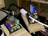
I can't get signal to DDC, When I use isolator pi ll between rpi3 and Q7. when I take it out of systems, I get signal to DDC and sound in my audio system. Is there something with the software I have to do or put it in master mode, now it is in slave mode.This used to be my setup, consisting of two stacks connected by a HDMI cable
https://www.diyaudio.com/community/attachments/_mg_2855_radiant_photo-jpeg.1246669/
Stack 1: RPI + IsolatorPi II + HDMIpi MKII
Stack 2: ReceiverPi DDC + FifoPi Q7 + DAC
I have modified Stack 1 to be RPI + IsolatorPi II + FifoPi Q7 + HDMI Pro II.
The new setup is:
RPI -> IsolatorPi II -> FifoPi Q7 -> HDMI Pro II ---> HDMI Cable ---> Receiver DDC -> FifoPi Q7 (with SC-PURE) -> DAC
So, I am using two FifoPi Q7, which makes a noticeable improvement. It reminds me of hearing Diretta's improvement when I heard it for the first time. The music is so clean and detailed across the whole frequency.
Surprising. How does doubling FifoPi Q7 in the signal path bring a noticeable improvement?
I use the same setup as you
RPI -> IsolatorPi II -> FifoPi Q7 -> HDMI Pro II ---> HDMI Cable ---> Receiver DDC -> FifoPi Q7 (with SC-PURE) -> DAC
Attachments
Last edited:
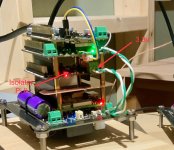
@geiren I am a bit puzzled because I can not see IsolatorPi II on your (left side of photo) stack. Under FiFoPi Q7 there seems to be some sort of a copper shield. Do you have a better photo of this stack?
What software do you use on RaspberryPi and what signal do you try to send (bit rate, kHz), where does the music come from?
What do you mean? Which software do you relate to?Is there something with the software I have to do or put it in master mode, now it is in slave mode.
What software do you use on RaspberryPi and what signal do you try to send (bit rate, kHz), where does the music come from?
maybe this is what he meant.What do you mean? Which software do you relate to?
Attachments
Makes sense. Then I run it in the Slave mode. I will double-check my Isolator Pi II configuration when I get back home.
in my configuration (FifoPI MA 1.5) I get no sound isolator II in slave mode.I will double-check my Isolator Pi II configuration when I get back home.
make sure you power the isolator II correctly, in my case I power it from the raspberry pi gpio.
I don't know how this is arranged with the FifoPi Q7 because it already has a built-in isolator.
see screenshot, manual FifoPIMA 1.5.
Attachments
@geiren I am a bit puzzled because I can not see IsolatorPi II on your (left side of photo) stack. Under FiFoPi Q7 there seems to be some sort of a copper shield. Do you have a better photo of this stack?
What do you mean? Which software do you relate to?
What software do you use on RaspberryPi and what signal do you try to send (bit rate, kHz), where does the music come from?
software on rpi is ropieee xl
the music com from roon
IsolatorPll is right over the copper shield
I will try it in Master mod.
Attachments
Last edited:
I don't see the isolator II either.What I don't see on @geiren photo is that there is any IsolatorPI but if there is one but somehow hidden, then I don't see power supply cable for it.
- Home
- Source & Line
- Digital Line Level
- Asynchronous I2S FIFO project, an ultimate weapon to fight the jitter