As Ben said, Google is your friend...
This is probably the single best page with PSU info for amplifiers - Decdun PSU page
This has lots of good info - https://www.instructables.com/Wire-Up-a-Fused-AC-Male-Power-Socket/
Rod Elliot diagram from excellent article here - Power Supply Wiring Guidelines
I would suggest that L ("hot") lead from the IEC socket always goes first to the fuse, then to the switch. The reason is that there is a small but finite chance that the switch could develop a short from hot to chassis, resulting in an overcurrent fault. The probability of this is, of course, a function of the switch design and construction. An all-plastic switch would reduce the risk.
OK gang, just a note that I've updated the "Parts: The Rest of the BOM" post based on what I've learned so far, with an updated Mouser cart (not everything is in stock, but such is life) that now includes connectors and corrections, plus things you'll need to get at the hardware store, and input/speaker wire recommendations (sure to stir controversy!):
Parts: The Rest of the BOM
Parts: The Rest of the BOM
^thanks. I finally figured out how the fuses install in the Shurter fused IEC. I was 😕 for a bit
My experience has been that the 2A fast-blow fuse supplied with the back panel kit is too small for the Aleph J. At least, that's what I've concluded after blowing 3 of them and substituting a 3A slow-blow alternative, which appears to be working fine.
I will include that tip in my revision of the power supply blog post, and I've already added 3A slo-blo fuses to the "Parts: The Rest of the BOM" post.
I will include that tip in my revision of the power supply blog post, and I've already added 3A slo-blo fuses to the "Parts: The Rest of the BOM" post.
Success! Power supply works. Used dim bulb tester with 100w bulb, lit up momentarily, then faded out, as it should. Measured just about 26v, both + and -.
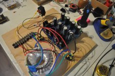
Here you've separated the heatsink portion from the cap section so wiring is a bit deceiving.
Can I test without thermistors?
A wiring question if I may: I've tested for continuity and have pairs marked A & B.
A & B go to their respective bridge rectifier.
From the PS to the BR I have the neg. wires crossed. The part A side neg. goes to the B side +. Visa versa. I believe this is correct?
Thanks. Out for a head clearing walk.
Test what? Just your PSU? How? With a dim bulb tester, hopefully? Yes, you can, but why?
Tested what for continuity? Primaries or secondaries? You need to check both. If you're asking about testing w/o thermistors, have you wired your mains/primaries etc. to a terminal block?
Yes, the secondaries go to the rectifiers.
Not sure what you mean re: your crisscrossing of negative wires. Pics are always very, very helpful. I posted a diagram earlier that may be of help if you're using an Antek transformer. It's color coded per the OPs build guide.
Head clearing is excellent. From what I can see you are proceeding methodically and asking questions.
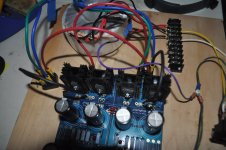
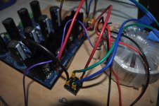
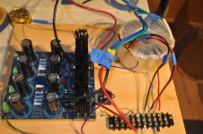
Sorry about the shadows. I have A & B side bridge rectifier marked.
A pair of primary wires to one, B primary's to the other'
The A red wire from the PS goes to the A rectifier, B red to B rectifier.
I have the B side neg. wire from the PS going to the A side rectifier & A side neg. to B side pos.
A pair of primary wires to one, B primary's to the other'
The A red wire from the PS goes to the A rectifier, B red to B rectifier.
I have the B side neg. wire from the PS going to the A side rectifier & A side neg. to B side pos.
Attachments
You're confused? I'm confused. 😕
You have a bridge rectifier feeding another rectifier bridge (four discrete rectifiers) for both V+ and V- on the PS board. You only need one or the other, either the monolithic bridge rectifiers or the on-board discrete rectifiers.
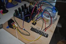
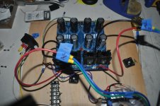
Also the monolithic bridge rectifiers could possibly overheat if not bolted to a heat sink such as the bottom plate of a chassis. You have yours on a piece of wood.
You have a bridge rectifier feeding another rectifier bridge (four discrete rectifiers) for both V+ and V- on the PS board. You only need one or the other, either the monolithic bridge rectifiers or the on-board discrete rectifiers.
Also the monolithic bridge rectifiers could possibly overheat if not bolted to a heat sink such as the bottom plate of a chassis. You have yours on a piece of wood.
You have two sets of rectifiers. That's admirable, but it's not the way it's intended. If you're running the rectifiers on the PCB, then you don't need the monolithic rectifiers. I love that you were cool enough to post your pictures. This helps everyone learn.
What would you prefer to use, the monolithic or the ones you mounted to your boards?
If you're confident you've mounted the ones to the boards correctly, then... you may as well use those.
Again, you are to be admired for posting. That's how we can all help.
Edited to add - Ben and I were typing at the same time. 🙂
Last edited:
The monolithic are the units with the heat sink bolted to them on the PS board?
If I use those, the units I have screwed to the wood can be shelved and the transformer wired straight to the PS board? If so that will clean things up.
If I can put 120v to it using my DBT and it passes with the thermistors that would speed things up as I could put it in it chassis and then wait on delivery of the thermistors.
The discrete rectifiers with heat sinks are the ones soldered to the PS board. You can delete the monolithic bridges (the square units - they contain four rectifier diodes each).
The thermistors slow down the charging of the power supply capacitors. You can test without them in place, especially if you use the dim bulb tester as the DBT limits the maximum current.
The thermistors slow down the charging of the power supply capacitors. You can test without them in place, especially if you use the dim bulb tester as the DBT limits the maximum current.
Seriously, it is very cool that you posted your pictures. It helps everyone learn, and you may save someone from following a similar path.
It may be valuable to the OP to describe what you found confusing and how you reached this point. Did you read the blog?
Once you rewire it, you may consider posting a diagram of how you did it along with some pictures.
It may be valuable to the OP to describe what you found confusing and how you reached this point. Did you read the blog?
Once you rewire it, you may consider posting a diagram of how you did it along with some pictures.
I'm using a single pole switch with the DBT. Tomorrow I'll go after a DPST unit and try again. I need fuses. The 2A fuses I had blew.
What is the VA of your transformer? The 2A fuse may be too small. Size of fuse should be VA/120V for North America. So if it's 300VA, fuse: 300VA/120V = 2.5A. Since you do not have the thermistors in yet, the surge current at turn-on may be higher, so 3A, and slow-blow. If your transformer VA is higher, size accordingly.
The fuse blowing could be because it is undersized, or it could be because of a short due to wiring error. Did you check the transformer primary and secondary wire pairs for continuity before connecting it all up?
I don't see how changing from a single pole switch to a double pull switch would make a difference. The switch and bulb should be on the live line. I don't have a switch on my DBT as I use the amplifier switch during the test.
- Home
- Amplifiers
- Pass Labs
- Aleph J build guide for noobs