
I actually didn't know that continuity testing was important for the secondaries, as well as the primaries, so I just got lucky. So thanks for that tip -- I will definitely include it in the revisions!
The idea for a video showing the dim bulb start up is a good one. I'll try making one!
Definitely!
Awesome!
I also like the idea of doing a wiring diagram for the power supply hookup, but I'm not sure how to do that neatly. I don't have any CAD software. If anyone wants to take a crack at it, or knows someone who has already done it, I'd be grateful.
Here are the ones I created for my own use when I was trying to visualize it all. If you choose to use them and/or would like some mods/additions, let me know. Just (as you've always done) be sure to note that this is for 120VAC operation.


Edited to ask - Do you need from secondaries to rectifiers and rectifiers to CRC?
I mean the plastic feet that come with the 4U Deluxe chassis. But I will clarify!
I thought that's what you may have meant. The holes to secure the bottom panel are for that purpose only, I believe. You'll use the sheet metal screws (at least in my kit). I read in another thread that there may have been some mods, so please check yours.
In my case, I needed to drill holes in the bottom panel for my feet. That seems to be common among others. So, just give it a look in case there is a new spec.
Last edited:

Just in case it may be helpful...

I used the wiring coloring from your guide and tweaked mine. Note: No one has reviewed any of these for exact electrical terms / correctness. They were good for my personal use, but If you're going to put it in a guide, I'd love for someone with 'real' knowledge to chime in. I love to help out where possible/practical, but I'm still a noob. I make LOTs of errors.
I used the wiring coloring from your guide and tweaked mine. Note: No one has reviewed any of these for exact electrical terms / correctness. They were good for my personal use, but If you're going to put it in a guide, I'd love for someone with 'real' knowledge to chime in. I love to help out where possible/practical, but I'm still a noob. I make LOTs of errors.
Wall socket tester, available at many stores:
Have one, my sockets are all good just jesting about my paranoia re guarding these fuses in neutral and hot.
I always double checked the FirstWatt PS drawing to line up from the plug/fuse IEC device all the way to the plug by continuity check.
This said, I have seen some preamp (not Pass related) that show fuse on the "big" blade style. I will look that up and comment later.
Thanks,
Russellc
As Ben said, Google is your friend...
This is probably the single best page with PSU info for amplifiers - Decdun PSU page
This has lots of good info - https://www.instructables.com/Wire-Up-a-Fused-AC-Male-Power-Socket/
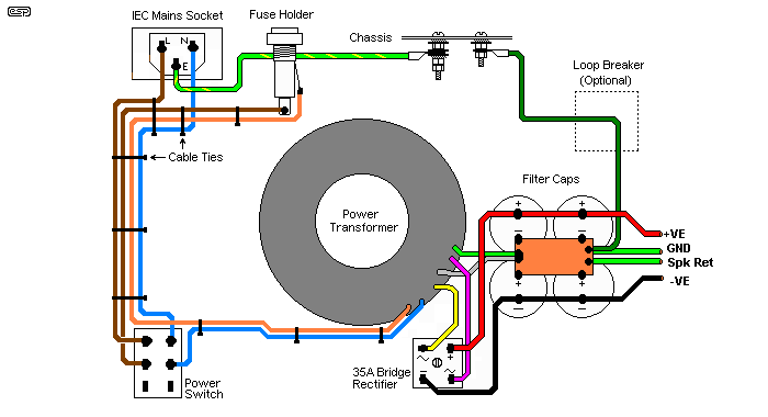
Rod Elliot diagram from excellent article here - Power Supply Wiring Guidelines

This is probably the single best page with PSU info for amplifiers - Decdun PSU page
This has lots of good info - https://www.instructables.com/Wire-Up-a-Fused-AC-Male-Power-Socket/
Rod Elliot diagram from excellent article here - Power Supply Wiring Guidelines
Last edited:
Google is your friend:
This is how I have always done it previously. Here, in post 17791, there is an example of the "RAW" PS, where fuse is in leg that goes to the larger blade. I have no doubt both the FirstWatt version here and Salas RAW are correct, just got me temporarily mixed up.
Simplistic NJFET RIAA
Thanks for your response, much appreciated.
Russellc
Definitely!
Awesome!
Here are the ones I created for my own use when I was trying to visualize it all. If you choose to use them and/or would like some mods/additions, let me know. Just (as you've always done) be sure to note that this is for 120VAC operation.
View attachment 898661
View attachment 898662
Edited to ask - Do you need from secondaries to rectifiers and rectifiers to CRC?
I thought that's what you may have meant. The holes to secure the bottom panel are for that purpose only, I believe. You'll use the sheet metal screws (at least in my kit). I read in another thread that there may have been some mods, so please check yours.
In my case, I needed to drill holes in the bottom panel for my feet. That seems to be common among others. So, just give it a look in case there is a new spec.
On feet, I drill the bottom cover and mount feet to that. Hole then drilled in perforated pan large enough to clear bolt and nut. That way, I can remove bottom cover, feet come with it as not attached to perforated pan.
Russellc
Great call out! 🙂 I raise my perforated plate about 2cm above the norm from the bottom panel, so I never considered your situation. With the inner perforated plate mounted per the diagram (with the "legs" facing down), are you saying there is not enough clearance for the remainder of the bolt + the nut in your situation? There should be enough clearance, but I may be missing something. With that said, I've never built it per the spec sheet... soooooo... 
As Ben said, Google is your friend...
Rod Elliot diagram from excellent article here - Power Supply Wiring Guidelines
Why google if there‘s rod? [emoji846] (and of DIYA, but which, alas, is highly dependent on google)
The article and guideline above motivated me to ditch those all in one solution and go for a fully separate inlet-fuse-switch method.
Count me in at the goldsmith/plumber/electrician-lobby 🙂
The holes to secure the bottom panel are for that purpose only, I believe. You'll use the sheet metal screws (at least in my kit). I read in another thread that there may have been some mods, so please check yours. In my case, I needed to drill holes in the bottom panel for my feet. That seems to be common among others. So, just give it a look in case there is a new spec.
Right, I'm intending to avoid any further drilling. Drilling metal is the kind of thing that intimidates n00bs (at least it intimidates me!). So you can avoid drilling for the feet if you just get longer machine screws (in place of the sheet metal screws) that can secure the feet and the bottom panel at once. I will hopefully photograph all this when I get to the final buttoning up post.
For the wiring diagram, here's my absolute favorite example (NOTE: this is for his double transformer 220v UK set up, so NOT suitable for our US single transformer). Anyone know who he is? He's The DIY Audio Implementer on YouTube, and he's on the DIYAudio forums somewhere. I'd love to know how he did that wiring diagram.
Last edited:
I am going to start doing it as Zenmod advised me, use some spacers and get longer screws to give space for wiring, feet bolt heads etc. Some flip it upside down as well, so far I assembled them as intended and there is a little space between bottom cove and perforated floor. Not much....
Russellc
Russellc
As far as RAW supply in the Salas unit, I will have to inquire there to know why fuse is in side going to the "big" blade, which is neutral. I am sure there is a reason.😕
Russellc
Russellc
Some transformers have dual primary leads so they can be configured for different wall power, 120, 220 or whatever is what I thought?
Russellc
Yes of course, but that's not what I'm talking about. With Antek's lead color scheme, (secondary A has 1 green and 1 blue lead, secondary B also has 1 green and 1 blue lead), it's possible to hook up one lead of secondary A and one lead of secondary B to rectifier bridge A; and another lead of secondary A and one lead of secondary B to rectifier bridge B.
Or you could wire it correctly, with both leads of secondary A connected to rectifier bridge A, and both leads of secondary B connected to rectifier bridge B.
Both of the above scenarios will look exactly the same to the human's eye, but of course are very different scenarios to the electrons.
Since the primaries are also 1 red, and 1 black lead each, it's very possible (likely?) that you can make a similar mistake wiring up the primaries, if you don't use a DMM to verify which red wire is connected to which black wire.
Just another reason to always use a dim-bulb tester 🙂
Well, it's easy if you are careless. All it takes is a few seconds with a multimeter. If that's too much for a builder, then they should get someone to do it properly for them. Or, if found confusing one could stick to transformers with only one set of primaries. Of course, then there are the secondary pairs...yeah you could wire them wrong if you don't check. Even then it is easy to see a mistake, think you are correcting and mess it up again.
Sorting primary and secondary leads is just part of it.
This electrical stuff isn't to be dumbed down, it can be dangerous. There is a learning curve here, and it can be unforgiving.
If you are building and just guess at the pairs, good luck with that. If something is unclear, there is no dishonor in asking, I have to all the time!
Russellc
Last edited:
I wasn't suggesting that it was difficult to check, or that someone who's never built an amp like this before with Antek transformers was careless for not realizing that it needed to be checked. Other transformer manufacturers like Toroidy and Avel-Lindbergh use better color schemes for their lead wires that make it harder to screw up.
But again this is a guide that's meant for beginners. Yes it's an easy check, but also something that's easy to overlook if you've not done this before. It may be an obvious and trivial matter to someone with as much experience as you, but you aren't the target audience for this guide.
Hence my suggestion to mention it in the guide.
Last edited:
Yes but your "target" audience needs this info! Primary and secondary wires only go one way, and the mistake you point out happens a lot. Many get the secondary wires to rectifiers right, some don't.
Those that don't, either didn't check, or did, then got distracted and still hooked them up wrong.
This is what is important to noobs...just because they look like pairs doesn't mean they are.
Measure them, always. Then what the eye sees matters not.
BTW, yes I've been at this for a minute, and have successfully built many. That's only because I can solder well, I can identify parts fairly well, and follow instructions. I think my best skill is the ability to see when I'm approaching "over my head," don't assume and ask those more knowledgeable.
I'm really not one of the ones who knows a lot, there are many here who do. I have zero electronics background, everything learned here from others.
I guess the one lesson here is don't assume anything , when you get there ask. I ask all sorts of stuff that shows my total ignorance here all the time.
On the other hand, it's always good to ask questions. When you need advice, I usually ask the knowledgeable guys here. Pico, 6l6, zenmod, many others. Papa joins in all the time too! Sorry for the many knowledgeable folks here who have helped me that I didn't mention, we are blessed here!
Noob on,
Russellc
Last edited:
Hmmm, before it sounded like you were arguing against my suggestion, now it sounds like we're both arguing in favor of it. 🙂
Anyway, cheers and build on!
Anyway, cheers and build on!
- Home
- Amplifiers
- Pass Labs
- Aleph J build guide for noobs