Last of the pieces ordered. LED's, thermister, diode & a few other small items.
I'll be able to put the Class D's to rest when this is finished.
I'll be able to put the Class D's to rest when this is finished.
OK, while many of you are speeding ahead, I'm just now ready to test the power supply section. Two questions:
1. which fuse goes in which position in the power inlet module? I'm using the Schurter from the back panel kit, which has two fuses of different values.
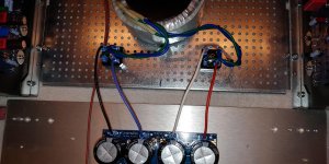
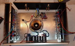
2. anyone see anything drastically wrong in the photos? I've mounted the filter cap board to the front panel to keep things roomy. That meant an additional terminal block for the GND-to-CL60-to-chassis connection, and I assume connecting to the same chassis ground as the safety earth and transformer ground wire makes sense?
1. which fuse goes in which position in the power inlet module? I'm using the Schurter from the back panel kit, which has two fuses of different values.
2. anyone see anything drastically wrong in the photos? I've mounted the filter cap board to the front panel to keep things roomy. That meant an additional terminal block for the GND-to-CL60-to-chassis connection, and I assume connecting to the same chassis ground as the safety earth and transformer ground wire makes sense?
Attachments


What? Uh oh....I guess I have been doing this all wrong these years. I assumed the fuses should both be the same, IIRC 3 amp slo-blo is what I used.
How should I have been doing this? I guess I totally missed the boat on this one!😱
Not sure I even remember mine coming with fuses?
Russellc
How should I have been doing this? I guess I totally missed the boat on this one!😱
Not sure I even remember mine coming with fuses?
Russellc
OK, while many of you are speeding ahead, I'm just now ready to test the power supply section. Two questions:
1. which fuse goes in which position in the power inlet module? I'm using the Schurter from the back panel kit, which has two fuses of different values.
2. anyone see anything drastically wrong in the photos? I've mounted the filter cap board to the front panel to keep things roomy. That meant an additional terminal block for the GND-to-CL60-to-chassis connection, and I assume connecting to the same chassis ground as the safety earth and transformer ground wire makes sense?
What's that white square thing @ 10:00 next to the transformer?
And another question. The large washers on the transistors. Do they serve a pourpose? Mine are a bit smaller.
Last edited:

Thanks for posting those photos.
Quick question- what gauge wire you using? 14AWG from the mains? then 16 after the transformer...?
Quick question- what gauge wire you using? 14AWG from the mains? then 16 after the transformer...?
OK, while many of you are speeding ahead, I'm just now ready to test the power supply section. Two questions:
1. which fuse goes in which position in the power inlet module? I'm using the Schurter from the back panel kit, which has two fuses of different values.
2. anyone see anything drastically wrong in the photos? I've mounted the filter cap board to the front panel to keep things roomy. That meant an additional terminal block for the GND-to-CL60-to-chassis connection, and I assume connecting to the same chassis ground as the safety earth and transformer ground wire makes sense?
What? Uh oh....I guess I have been doing this all wrong these years. I assumed the fuses should both be the same, IIRC 3 amp slo-blo is what I used.
How should I have been doing this? I guess I totally missed the boat on this one!😱
Not sure I even remember mine coming with fuses?
Russellc
If both the neutral and live lines are fused, the neutral line fuse should be of higher value such that the live line fuse will blow first.
The reason for that is if the neutral line blows instead, the live line is still active. Then if there is a short to the chassis, the chassis is live and if you touch the chassis and if you are grounded, electricity may pass through you to ground - a dangerous thing.
^^Exactly this.
In some places it's not allowed to fuse the neutral, so a 10A fuse on neutral should insure the properly-sized fuse on live to blow first.
In some places it's not allowed to fuse the neutral, so a 10A fuse on neutral should insure the properly-sized fuse on live to blow first.
So what's the point of having both live and neutral fused? Why even bother using a fuse on the neutral?
Last edited:
Oh ok. So if you were buying your own IEC power entry module, it'd be ok to get one with just 1 fuse, and fuse only the live then, correct?
Yes, and a single fuse IEC module will have the fuse in the live line. Then no problem unless your wall socket is wired incorrectly.
Also identify the live output of the IEC module so that the power switch is installed in the live line if switch is not built into the module. You do not want the neutral switched and the live unswitched. No problem if your switch switches both lines.
Also identify the live output of the IEC module so that the power switch is installed in the live line if switch is not built into the module. You do not want the neutral switched and the live unswitched. No problem if your switch switches both lines.
Quick question- what gauge wire you using? 14AWG from the mains? then 16 after the transformer...?
I'm using 16 gauge for all the power wiring. You could go with 14 gauge, but make sure the connectors you're using will support it. I'm using Panduit connectors for the ring and Faston connections (details about which ones will be in the next blog post, and then I will update the Mouser cart, too), which support 14-18 gauge, I think.
What's that white square thing @ 10:00 next to the transformer?
That's another terminal block, for connecting the CL60 thermistor between chassis and power supply board GND. If you mount the power supply board on the chassis floor, then you can just connect one CL60 leg to the board GND, and the other leg to the chassis floor. But since I'm mounting the board on the front panel, I needed a safe way to connect the CL60 to the chassis floor (and figured I'd just used the chassis ground that's already there for the IEC safety earth and the transformer purple ground wire.
I went with the white ceramic block (instead of the black plastic block) because someone on the forum suggested this connection could get hot in a fault case, so better to go with ceramic.
And another question. The large washers on the transistors. Do they serve a pourpose? Mine are a bit smaller.
Seems some people use them, some people don't. The DIYAudioStore backpanel kit for the 4U Deluxe chassis comes with a bunch of those large fender washers, so I figured might as well use them. I imagine the concept is that they spread the mounting force across the entire transistor, potentially making a better contact with the Keratherm and heat sink?
Is there a problem with using a wood enclosure?
Hm, that one is beyond my skill to answer, but obviously there are several connections that assume a chassis ground, so you'll need to sort those all out and provide a grounding solution. And the rectifier bridges will need some kind of heat sinking.
Certainly not something I'd recommend for n00bs. 🙂
I've built a few amps in the past using wood. Wondering why this would be different.
I could put a metal floor on it.
I could put a metal floor on it.
Last edited:
I've built a few amps in the past using wood. Wondering why this would be different.
I could put a metal floor on it.
You might get more informed answers if you posted this question in 6L6's "illustrated build guide" thread. For the n00bs guide that I'm putting together, I'm hoping to keep it as simple as possible. Sourcing or building your own wood enclosure with metal base and attached heat sinks adds a lot of complexity for those who have not "built a few amps in the past". 🙂
- Home
- Amplifiers
- Pass Labs
- Aleph J build guide for noobs