Congrats! Nothing left to do but wire it up! Now that you have the power supply working I suggest you test the amp boards before putting the whole thing together. I didn’t test mine individually until the whole thing was built and lost several hours of taking apart stuff when one channel was dead due to a bad JFET. Good luck!

Congrats! Nothing left to do but wire it up! Now that you have the power supply working I suggest you test the amp boards before putting the whole thing together. I didn’t test mine individually until the whole thing was built and lost several hours of taking apart stuff when one channel was dead due to a bad JFET. Good luck!
Is there a good way to test an amp board on its own if you don’t have a lab power supply?
I would love to see this (or any other wooden enclosures you've made). I thought I might have a wooden front piece made (very much out of my skillset) using the existing front panel as a template (for threaded inserts, say, etc.).
^^^outstanding and thanks again. Black Walnut it is, homegrown
The only 100% non-metal chassis I know of are those outlandish DNM machines.
Vintage-gear, tube amps etc all have at least a front, back or baseplate in metal...
Vintage-gear, tube amps etc all have at least a front, back or baseplate in metal...
Is there a good way to test an amp board on its own if you don’t have a lab power supply?
Yes, you can build an amplifier successfully without a lab power supply. I would venture a guess that most of the builders here on diyAudio do not have a lab power supply.
The most important thing for a troublefree build is to build the power supply and amplifier boards correctly. That may seem obvious but there are many instances of diyers with build problems on diyAudio. That means taking your time, identifying parts before installing and soldering. Measure all resistors to confirm correct values before stuffing and soldering to boards. Compare with schematics and confirm. Confirm all component values and pin configurations and orientations of capacitors, diodes, transistors etc, before installing and soldering. Follow instructions where available. The same goes with wiring. Check and double check each wire location and placement. When in doubt, ask, don't assume or guess. The extra time taken will seem like nothing compared to the time of troubleshooting if you rush things and end up with a mistake.
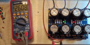
The amplifier should be built and tested in stages. First build the power supply and test it. For the first powerup, connect it to a dim bulb tester. If it passes the dim bulb test, remove the dim bulb tester and power up and test for correct voltage and operation. If it passes the test then you have a functioning power supply.
The next step is to build one channel of the amplifier board. Connect it to the tested power supply and connect meters to measure the recommended voltages, and power up with the dim bulb tester in place. If it passes the test and the recommended measurements and adjustments are as expected, then remove the dim bulb tester and power up again, and adjust and measure as required.
Then build the other channel and repeat. It is best not to build both channel boards together to avoid identical mistakes being repeated on the second board.
After the first board is finished and tested successfully, it can also be used for reference when building the second board.
The key is to build and test in stages, and use a dim bulb tester with each initial power up.
One point I like to add to Ben's post is to get in a habit of measuring
and verifying that the voltages on output connectors of the PS pcb are low
before handling them; you want to make sure the PS has been sufficiently
drained.
This is particularly important after the standalone PS power up test where there
is no load attached. When you power down, the PS will still be almost fully
charged and it will take a while for the LEDs + bleeder resistors to drain
the PS to a safe level.
+1 to the gentlemen above. They both saved me a number of times throughout many builds. 🙂
Just to add a bit more from a noob's POV.
Benchtop / standalone / 'lab' supplies can be had on a relative budget. However, the OP mentioned that this guide is focused toward people that are likely to just build this amp, and a tight budget was considered for tools and even wire by the foot. So, adding what could be 10% to 20% or more of the total build cost toward a tool is a tough choice when the existing / tested PSU is available.
tl;dr - I recommend using the existing PSU in this case, but yes, having a benchtop supply is nice.
Lastly, although it has been covered a number of times in other threads, it is important to allow (ballpark) 20 seconds or so for the CL-60s acting as the soft start to cool after each power down. Even if the LEDs go dim fairly quickly after connecting the amp board(s), the CL-60s may not have gone back to their 'cool' resistance. If they are not at (or close to) their cool temp resistance, it is possible to blow a fuse. If spare fuses aren't available immediately, it's a hassle. I know from experience.
tl;dr - Just another reason to not flip the power off and on again quickly.
Thanks for the posts above from @ItsAllInMyHead, @Dennis Hui, and @Ben Mah. Great advice there! I will try to incorporate it into my blog posts in the n00bs guide.
Speaking of which, I've posted the next installment, documenting my power supply assembly and test.
Building: Assembling and Testing the Power Supply
For the benefit of future n00bs, please let me know if I've goofed anything up.
I will next be updating the saved Mouser cart and supplementing the "BOM: Everything Else" post with some additional advice on connectors, machine screws, and input/output wire options.
Nice work! One tip I picked up somewhere was to tin the XLR cups before you install them. Then when you need to solder the wires in later, tin the leads and then it is very simple to solder them to the cups by just heating the cup and wire together. Does that make sense?
JMacII, Yes, that makes life much easier.
flohmann - Nicely done as always.
I have a few questions / comments.
"The screws holding the bottom panel will also double as the footer mounting screws."
What do you mean by "footer" in this sentence?
In the section for mounting the binding posts, you do an excellent job explaining the keying. It may be nice for first-time builders have some context as to why it may matter. It's particularly important if you use spades. I prefer my spades to enter from the top. Of course it works both ways, but it's a matter of preference.
It's a small nit to pick, but for your mains earth to chassis wiring, the strain relief for your connector isn't too far up the insulation. Would I change it... maybe not, but it's worth a mention.
re: testing with the dim bulb tester. It may be helpful to describe your experience re: timing with the 100W bulb. If you're feeling particularly generous and have the skills, a video would be incredible. If that's not practical, a more in-depth description may be appropriate. If it does not dim, stress could be placed on turning the power off ASAP. The dim bulb will not save you indefinitely.
Something like...
"Third, time to throw the switches and power it up. You should see the bulb briefly light and then dim (indicating that the filter capacitors have charged) and the two LEDs on the power supply board should light up."
Keep your hand on the power switch, if the bulb does not immediately begin to dim, then cut the power. If the bulb dims immediately, then you can grab your DMM to check the rail voltages.
Eventually, when you get to testing the boards and then testing / setting the final tweaks, it's inevitably asked why to remove the dim bulb tester or how it works / why etc.
Here's my reference post. https://www.diyaudio.com/forums/pass-labs/241729-aleph-illustrated-build-guide-264.html#post5432381
Just a few thoughts. I am sure others will see things I did not and/or offer alternate/additional perspectives. Also, as always, I barely know anything about this, but I do remember my struggles and where I had a ton of questions. I also have links to lots of posts from when I had questions. 🙂
Again, I think the work you're putting into this is well worth it. Noobs rejoice and give thanks!
Looks great as always, flohmann.
I'd suggest a couple additions if possible:
1) It would probably be helpful if you could post a PS wiring diagram (not in schematic form; something more pictorial with transformers, bridge rectifiers, terminal blocks etc that look like the real thing) to make it 100% clear which wires go where. Might be good to do the same thing with signal wiring when you get to the point of wiring input jacks to amp boards to output posts.
2) Since Antek toroidals have largely become the de-facto DIYAudio standard (for North American builders anyway) it may be a good idea to point out that you need to use the continuity check function on your DMM to ensure you're correctly wiring 1 secondary to 1 bridge, and wiring the primaries correctly, since they have dual primaries and dual secondaries that use the same color combination for both pair of primaries and both pairs of secondaries. I almost learned this the hard way the first time I used Antek transformers, but luckily I was using a Dim-bulb tester to test. Other transformer manufacturers like Avel-Lindbergh and Toroidy prevent this with more fool-resistant lead colors. I'm not sure why Antek doesn't realize the huge potential for mis-wiring with their current wire color scheme and fix it, but that's how they've made them for over 10 years now...so I don't expect them to change it anytime soon.
Otherwise, looks great and keep up the good work!
Thanks to all for the excellent feedback. I will make appropriate revisions later this week.
I actually didn't know that continuity testing was important for the secondaries, as well as the primaries, so I just got lucky. So thanks for that tip -- I will definitely include it in the revisions!
The idea for a video showing the dim bulb start up is a good one. I'll try making one!
I also like the idea of doing a wiring diagram for the power supply hookup, but I'm not sure how to do that neatly. I don't have any CAD software. If anyone wants to take a crack at it, or knows someone who has already done it, I'd be grateful.
I mean the plastic feet that come with the 4U Deluxe chassis. But I will clarify!
The fuses that came with the back panel kit were a really tight fit, so. much so that I ended up crushing one after my initial test. And then the first replacement fuse I tried blew immediately. The second replacement fuse seems to be holding so far, so I'm hoping all is well...
I actually didn't know that continuity testing was important for the secondaries, as well as the primaries, so I just got lucky. So thanks for that tip -- I will definitely include it in the revisions!
The idea for a video showing the dim bulb start up is a good one. I'll try making one!
I also like the idea of doing a wiring diagram for the power supply hookup, but I'm not sure how to do that neatly. I don't have any CAD software. If anyone wants to take a crack at it, or knows someone who has already done it, I'd be grateful.
"The screws holding the bottom panel will also double as the footer mounting screws."
What do you mean by "footer" in this sentence?
I mean the plastic feet that come with the 4U Deluxe chassis. But I will clarify!
The fuses that came with the back panel kit were a really tight fit, so. much so that I ended up crushing one after my initial test. And then the first replacement fuse I tried blew immediately. The second replacement fuse seems to be holding so far, so I'm hoping all is well...
Looks great as always, flohmann.
I'd suggest a couple additions if possible:
1) It would probably be helpful if you could post a PS wiring diagram (not in schematic form; something more pictorial with transformers, bridge rectifiers, terminal blocks etc that look like the real thing) to make it 100% clear which wires go where. Might be good to do the same thing with signal wiring when you get to the point of wiring input jacks to amp boards to output posts.
2) Since Antek toroidals have largely become the de-facto DIYAudio standard (for North American builders anyway) it may be a good idea to point out that you need to use the continuity check function on your DMM to ensure you're correctly wiring 1 secondary to 1 bridge, and wiring the primaries correctly, since they have dual primaries and dual secondaries that use the same color combination for both pair of primaries and both pairs of secondaries. I almost learned this the hard way the first time I used Antek transformers, but luckily I was using a Dim-bulb tester to test. Other transformer manufacturers like Avel-Lindbergh and Toroidy prevent this with more fool-resistant lead colors. I'm not sure why Antek doesn't realize the huge potential for mis-wiring with their current wire color scheme and fix it, but that's how they've made them for over 10 years now...so I don't expect them to change it anytime soon.
Otherwise, looks great and keep up the good work!
Some transformers have dual primary leads so they can be configured for different wall power, 120, 220 or whatever is what I thought?
Russellc
The fuses that came with the back panel kit were a really tight fit, so. much so that I ended up crushing one after my initial test. And then the first replacement fuse I tried blew immediately. The second replacement fuse seems to be holding so far, so I'm hoping all is well...
Have a link for those fuses. I ordered a switch & don't thing it comes with a fuse.
^^Exactly this.
In some places it's not allowed to fuse the neutral, so a 10A fuse on neutral should insure the properly-sized fuse on live to blow first.
Point of clarification, (for me!) tracing all the way back to power cord to wall, neutral would be the large blade? Well, correct assuming your receptacle is properly wired? Or is it small blade? I thought it was small blade, but am starting to confuse myself.
I have noticed that when a fuse does blow, only one cooks so this is making sense to some degree. Can't believe I missed that one all these years.
Somehow I can see laying awake wondering if my receptacles are wired correctly....
Russellc
Last edited:
- Home
- Amplifiers
- Pass Labs
- Aleph J build guide for noobs