Try the hardware store. The locally owned franchise Ace or Tru-Value will have the plastic bins and a fighting chance of having them.
Nothing? I've checked polarity, again.
Is it possible to have the secondary's wired backwards? I have those connections split. Part A to pos. and part B to neg.
Is it possible to have the secondary's wired backwards? I have those connections split. Part A to pos. and part B to neg.
Attachments
Last edited:
Perhaps a silly question, but did you check your dim bulb tester on a known-working-good piece of electronics?
As simple as they are, I made an error with mine. Test the test gear.
As simple as they are, I made an error with mine. Test the test gear.
Please be more explicit. It's hard to do long distance diagnosis with no information.
Did the fuse blow? Did the bulb not light?
If the fuse did not blow, use your meter to check for voltage. starting at the AC in. Check for AC to the transformer primary,and at the secondary out to the rectifiers.
Also, what ItsAllInMyHead said.
Did the fuse blow? Did the bulb not light?
If the fuse did not blow, use your meter to check for voltage. starting at the AC in. Check for AC to the transformer primary,and at the secondary out to the rectifiers.
Also, what ItsAllInMyHead said.
Perhaps a silly question, but did you check your dim bulb tester on a known-working-good piece of electronics?
As simple as they are, I made an error with mine. Test the test gear.
I'm on it.
Fuse didn't blow and bulb didn't light. I'm checking the DBT now.Please be more explicit. It's hard to do long distance diagnosis with no information.
Did the fuse blow? Did the bulb not light?
If the fuse did not blow, use your meter to check for voltage. starting at the AC in. Check for AC to the transformer primary,and at the secondary out to the rectifiers.
Also, what ItsAllInMyHead said.
I understand the frustration and the mental exhaustion. You'll get it going soon. The DBT seems functional, if you are meaning that the bulb lit (maybe even brightly, but was consistent). I'm not sure what power your tube amp may draw on immediate startup and continuously, but if the bulb lights w/o dimming then it's most likely fine.
In essence, the bulb will go fully bright if there is a dead short or something that temporarily acts like a dead short (the filter caps before they're charged as an example). If the caps charge, then the bulb dims b/c the PSU is done drawing current. There's no load yet, and the caps are charged. You can also test it independently by just shorting your IEC end. Bulb should be fully bright. Full circuit with just a light bulb. A likely scenario is that your tube amp may not have a lot of filter capacitance and/or draws say over 200W. Another scenario is that you had the tube amp up and running with a full cap charge, unplugged it, the caps didn't discharge fully before you plugged it into your DBT and powered back up.
Generally, you need a bulb around 1.5 to 2x the power draw of the DUT. If it's under that, the bulb will glow (perhaps even brightly). If the tube amp isn't working with the DBT, that's okay.
See this article for what I consider a very nice explanation. It goes into far more detail that I could, and is written by someone that actually knows things versus copies and regurgitates them like I do.
Powering Your Radio Safely with a Dim-bulb Tester
See Ben Mah's post and run through it methodically. I'd suggest following his advice directly and not diverting. To be specific, measure and report exactly below with the DBT in place. Stop when you hit the first answer of no. Voltages should be close, but not necessarily exact. When you measure a result, let us know what you found.
Do you have 120VAC between hot and neutral at the IEC?
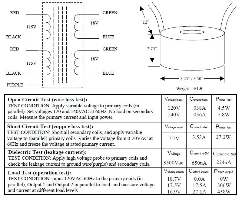
Do you have 120VAC across primary set A? Set B?
Do you have 18VAC across secondary set A? Set B?
Do you have -26VDC at V-?
Do you have +26VDC at V+?
After we have that, we can narrow things down a bit.
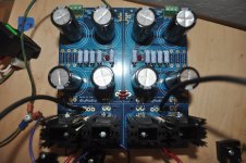
Your pics are pretty good, but if you already have or can jot down a basic sketch of your wiring diagram showing how you intended to hook everything up, it would also be helpful. If not, we may need more pics of specific areas.
🙂
In essence, the bulb will go fully bright if there is a dead short or something that temporarily acts like a dead short (the filter caps before they're charged as an example). If the caps charge, then the bulb dims b/c the PSU is done drawing current. There's no load yet, and the caps are charged. You can also test it independently by just shorting your IEC end. Bulb should be fully bright. Full circuit with just a light bulb. A likely scenario is that your tube amp may not have a lot of filter capacitance and/or draws say over 200W. Another scenario is that you had the tube amp up and running with a full cap charge, unplugged it, the caps didn't discharge fully before you plugged it into your DBT and powered back up.
Generally, you need a bulb around 1.5 to 2x the power draw of the DUT. If it's under that, the bulb will glow (perhaps even brightly). If the tube amp isn't working with the DBT, that's okay.
See this article for what I consider a very nice explanation. It goes into far more detail that I could, and is written by someone that actually knows things versus copies and regurgitates them like I do.
Powering Your Radio Safely with a Dim-bulb Tester
See Ben Mah's post and run through it methodically. I'd suggest following his advice directly and not diverting. To be specific, measure and report exactly below with the DBT in place. Stop when you hit the first answer of no. Voltages should be close, but not necessarily exact. When you measure a result, let us know what you found.
Do you have 120VAC between hot and neutral at the IEC?
Do you have 120VAC across primary set A? Set B?
Do you have 18VAC across secondary set A? Set B?
Do you have -26VDC at V-?
Do you have +26VDC at V+?
After we have that, we can narrow things down a bit.
Your pics are pretty good, but if you already have or can jot down a basic sketch of your wiring diagram showing how you intended to hook everything up, it would also be helpful. If not, we may need more pics of specific areas.
🙂
Last edited:
^outstanding and I'll get on it this morning.
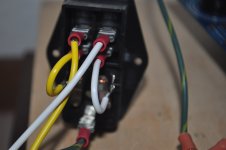
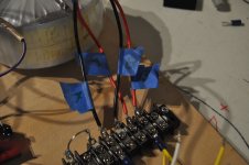
I have a quick question. The 4 wires going to the terminal strip are as shown in the drawings. I have the IEC wired with live going to red A and neutral to black B. No thermistors as of yet. Should I jumper A's & B's so everything has 120v?
I have a quick question. The 4 wires going to the terminal strip are as shown in the drawings. I have the IEC wired with live going to red A and neutral to black B. No thermistors as of yet. Should I jumper A's & B's so everything has 120v?
Last edited:
I get 120VAC betweel hot/neutral @ IEC
120VAC A primary measured @ terminal strip
1.9VAC @ secondary A & B
120VAC A primary measured @ terminal strip
1.9VAC @ secondary A & B
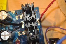
Install the thermistors. Also look at your transformer wiring again, it doesn't look right but I can't see everything.
check PM
check PM
Last edited:
I had to be away from the computer for a bit. If 6L6 is on the case via PM, you're in good hands. No need for me to comment further. Waiting to hear of success. 🙂
With the power Off (use a power strip with ON/Off switch), connect a power cord, then to IEC inlet.
Disconnect the Universal PSU to the transformer secondary.
1.) Transformer PRIMARY -Connect Red and Red together, and Black and Black together. Measure the resistance from Red-Red to BLK-BLK. You should not get 0 ohms or OL (open loop). What is the resistance? If not zero, proceed to the next step.
2.) Transformer SECONDARY - (Green-Blue, Green-Blue, as a pair based on the wiring diagram). Lets say GRN on top is G1 and BLU on top is B1(top pair), GRN at bottom is G2 and BLU at bottom is B2 (bottom pair). Measure the resistance for each pair. You should not get 0 ohms or OL (open loop). What is the resistance? If not zero, proceed to the next step.
3.)From IEC, connect Live to RED-RED and Neutral to BLK-BLK. Connect GND to chassis and static shield.
4.) Connect your DVM (voltmeter) to G1 (positive probe ) and B1 (negative Probe). Leave G2 and B2 open (use electrical tape to insulate it to avoid any accidental contact to metal).
5.) Set meter to measure AC volts.
6.) Turn on the power srtip
What is the reading on the meter in AC?
You should get about 18 Vac on the meter (record the reading for reference). If it is zero, as soon as you flip the switch, turn it back Off. Check connections.
Repeat steps 1-5 for the other secondary pair (G2 and B2), making sure to isolate the unused pair with electrical tape for safety.
When you are sure that the transformer is working properly, connect G1, B1 and G2, B2 to the Universal PSU board.
At power On, with the Universal PSU board connected, LEDs should be On. Measure V+ out (from V+ or V++) to GND on the board, then do the same to the other channel. Record the values.
If you have OL (open loop) reading in any of the resistance measurements, check meter setting or use a different meter if available. Otherwise, there's a problem in the transformer. The 1.9VAC reading you posted on the secondary sounds like you are measuring from the wrong secondary pair.
Hope this helps.
Hi Mkane77g - seems amandarae and I were typing at the same time.
Edited quite a bit for brevity and clarity b/c quite a bit of excellent information is in the post above.
Within your context of your issue. See schematic below. Look where the two thermistors are in the circuit. Look at your terminal block. No connections between the primaries. That's why I had asked earlier if you were using a terminal block when you asked if you could test w/o the thermistors in place. 🙂 Your latest pics were key.

So, you have a few options to proceed. Wait for thermistors or do a bit of rewiring.
Again, please allow at least one other person to confirm or say I'm nuts before proceeding. Also, if you have your fuses in place w/o the thermistors, they may (or may not) blow. I can't be sure. Proceed with that in mind.
Edited quite a bit for brevity and clarity b/c quite a bit of excellent information is in the post above.
Within your context of your issue. See schematic below. Look where the two thermistors are in the circuit. Look at your terminal block. No connections between the primaries. That's why I had asked earlier if you were using a terminal block when you asked if you could test w/o the thermistors in place. 🙂 Your latest pics were key.
So, you have a few options to proceed. Wait for thermistors or do a bit of rewiring.
Again, please allow at least one other person to confirm or say I'm nuts before proceeding. Also, if you have your fuses in place w/o the thermistors, they may (or may not) blow. I can't be sure. Proceed with that in mind.
- Home
- Amplifiers
- Pass Labs
- Aleph J build guide for noobs