Hi Mkane77g - seems amandarae and I were typing at the same time.
Edited quite a bit for brevity and clarity b/c quite a bit of excellent information is in the post above.
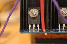
Within your context of your issue. See schematic below. Look where the two thermistors are in the circuit. Look at your terminal block. No connections between the primaries. That's why I had asked earlier if you were using a terminal block when you asked if you could test w/o the thermistors in place. 🙂 Your latest pics were key.
View attachment 899726
So, you have a few options to proceed. Wait for thermistors or do a bit of rewiring.
Again, please allow at least one other person to confirm or say I'm nuts before proceeding. Also, if you have your fuses in place w/o the thermistors, they may (or may not) blow. I can't be sure. Proceed with that in mind.
A rewire is no problem. I've been chasing wire for 40 hours.
Woo hoo! So, it seems that you've confirmed that your donut is working. I assume you followed the exceptional advice provided in #479. Step 3 being a very key part of the equation.
Now, look at the schematic vs. how you had your primaries wired before. Are you understanding?
Now, do you want to pause or move forward w/o the thermistors in place and have to add them later?
Edited to add - the answer to your post #473 was (as you know now)... YES! 😀 😀 😀
Now, look at the schematic vs. how you had your primaries wired before. Are you understanding?
Now, do you want to pause or move forward w/o the thermistors in place and have to add them later?
Edited to add - the answer to your post #473 was (as you know now)... YES! 😀 😀 😀
Last edited:
OK, so... how's it all hooked up now? Have you got everything back on your bench with the terminal blocks wired etc. primaries connected? Secondaries connected back to your rectifiers? Rectifiers to CRC board etc. etc.?
If no, do that.
If so, see post #472.
With DBT in place, let's hope we get a fast flash / dim this time. If not, pause again. If so:
Do you have 120VAC across primary set A? Set B? It darn well better be. 🙂
Do you have 19VAC across secondary set A? Set B? It darn well better be. 🙂
Do you have -26VDC at V-?
Do you have +26VDC at V+?
Again, voltages are estimates.
Note, I'm not sure what value fuse or fast / slow you put on your hot side. It may or may not love this if your IEC module is in place and fused.
Last edited:
Hi Mkane77g - seems amandarae and I were typing at the same time.
Edited quite a bit for brevity and clarity b/c quite a bit of excellent information is in the post above.
Within your context of your issue. See schematic below. Look where the two thermistors are in the circuit. Look at your terminal block. No connections between the primaries. That's why I had asked earlier if you were using a terminal block when you asked if you could test w/o the thermistors in place. 🙂 Your latest pics were key.
View attachment 899726
So, you have a few options to proceed. Wait for thermistors or do a bit of rewiring.
Again, please allow at least one other person to confirm or say I'm nuts before proceeding. Also, if you have your fuses in place w/o the thermistors, they may (or may not) blow. I can't be sure. Proceed with that in mind.
When I built 1st amp here, that part of the PS circuit (double CL-60s) confused me. It all came clear looking at it on a barrier strip in one of 6L6's build guides. If you havent already, compare to your wiring. Again, as long as you have been at it, you probably already have.
Russellc
You have a few mV where?
Take a couple photos of the setup now.
What diodes do you have in the bridges?
Take a couple photos of the setup now.
What diodes do you have in the bridges?

Probe V+ to GND
Probe V- to GND
If you probe + & -...
+ 26V + (-26V) is ... 0 or a few mV if it's off a touch on one side. 🙂
Either way if the bulb goes bright and stays bright... hmmmm...
Probe V- to GND
If you probe + & -...
+ 26V + (-26V) is ... 0 or a few mV if it's off a touch on one side. 🙂
Either way if the bulb goes bright and stays bright... hmmmm...
@mkane77g, I'm sorry you're having trouble. I see you're in good hands here and hope you sort it out. You've gone pretty far off piste from my n00bs guide, so I don't have much advice to contribute. :-(
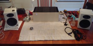
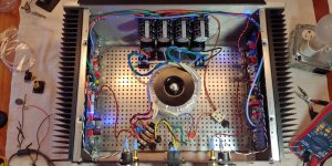
Good news on my end -- it's assembled and making music!
I did initial amp board hookup and bias/offset adjusting without assembling the entire chassis, just in case something needed fixing. But that all went great, so I assembled the whole thing (the chassis is kind of fiddly), tidied up my wire routing, hooked up the input jacks, and re-adjusted bias/offset. Finally, hooked up sacrificial speakers and an iPod and ... music! No hum, been playing for an hour+ so far.
One problem: the holes on the bottom cover don't quite line up with the holes in the heat sink rails. I probably will have to drill the bottom cover holes out until the screws can see the holes. Sigh. There's always something.
Oh, one other thing: I gave in to temptation and added a front-panel LED, using one of the blind holes meant for the optional handles. Had to drill out the hole, desolder V- amp board LED, solder in wires, solder wires to the blue LED, heatshrink all the exposed wire, and fit the LED into the hole. I'm reasonably happy with it.
I will be turning now to finishing up the n00bs guide blog, while listening to my Aleph J. THANKS SO MUCH TO ALL WHO HAVE HELPED HERE!
Attachments
WOOOOOOOOOOOOOOOOO!
😀 😀 😀 😀 😀
Congratulations!
Once again, your guide is an asset. I hope you enjoyed creating it so far, and it'll be phenomenal when completed.
Edited to add - DUH! Enjoy that sweet, sweet music
😀 😀 😀 😀 😀
Congratulations!
Once again, your guide is an asset. I hope you enjoyed creating it so far, and it'll be phenomenal when completed.
Edited to add - DUH! Enjoy that sweet, sweet music
So what voltages do you get when probing properly? I'm typing a lot, and I'm not getting a ton of info back.
"Light still on" is not informative. See numerous previous posts for specific questions asked. Once answered, I'll continue.
"Light still on" is not informative. See numerous previous posts for specific questions asked. Once answered, I'll continue.
Could the LED's be in backwards making then not work. I'm tempted to remove the heatsink/transistor portion and try the bridge rectifiers.
Light stays on. I get a few mv when I probe + & - on the ps board
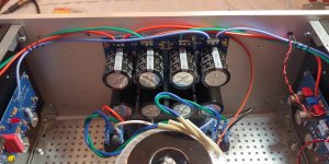
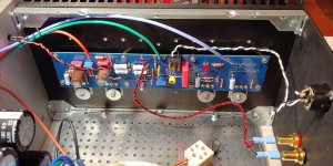
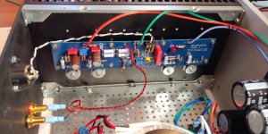
Please take a picture or pictures (preferably top view) of the complete rectifier-cap bank board showing the wiring from PSU to rectifier and rectifier to cap board and indicate where are you measuring and what did you measure (voltages).
It will be easy to sort it out if we can see the entire wiring and orientation. It might sound I am repeating what other people have already said, but when you post a picture, you have to capture the entire board and all the wiring connected to it clearly so we can see the board itself, the orientation of the parts, connectors, and wire terminations.
Please be patient, you will solve this in no time.
Abe
Last edited:
I'm getting .625V when probed properlySo what voltages do you get when probing properly? I'm typing a lot, and I'm not getting a ton of info back.
"Light still on" is not informative. See numerous previous posts for specific questions asked. Once answered, I'll continue.
Could the LED's be in backwards making then not work. I'm tempted to remove the heatsink/transistor portion and try the bridge rectifiers.
No, the LEDs won't have an impact. You continue carrying forward w/o covering the basics or answering basic things so I can help. I'll chalk it up to my inability to properly convey what needs to be done. I'll leave it to others. I need to get on to other things.
Hope you get it working soon! You'll love it. 🙂
- Home
- Amplifiers
- Pass Labs
- Aleph J build guide for noobs