That's more valuable than what I proposed wrt reducing a 1" compression driver, at least to me. Does anyone know what the inside diameter of the phase plug exit is on 1.4" and 2.0" compression drivers are (in general)? Which reminds me, I need to add a post to show the dimensions I used to print an internal ring for a DE250 in addition to the DE111. That will allow everyone to at least model internal rings for those drivers, or even a bare conical section inside the driver.I'd be perhaps more interested in e.g. HF146 (1.4"). With a ring one could get to a ~1" performance (which I still believe is good enough as it is)...
Does a cone shaped reduction like in post #12,428 cause the wavefront to deviate?All this will collapse once the real exit wavefront deviates from flat. I'd guess it won't hold up to 20 kHz with a real driver, but can be close. Definitely I would like to see it.
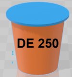
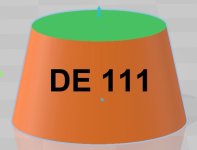
3D printed Internal Ring size dimensions that will fit into a B&C DE111 and DE250. This is not the exact shape of the conical exits, just a 3D print that fits snugly. Consequently, you will be able to safely fit your waveguide/internal ring design within these dimensions.
DE250: cone 24.5mm outside diameter, 102.08mm overall height (6.843° half angle). Cut to 25mm overall height. In addition, add a 28mm diameter 1mm tall spacer between the end of the plastic conical section and the flat surface of the compression driver. 25mm +1mm = 26mm overall height of cone and spacer. The DE250 uses a plastic conical section with three small internal ribs spaced about 8mm apart that rise ~0.25mm from the surface. That's why the cone O.D. is reduced from 25mm to 24.5mm. Also, you might be able to bore out the plastic conical section. The top part of the metal bore is 28mm diameter but I don't know if that diameter extends all the way to the phase plug.
DE111: cone 25mm outside diameter, 58.8mm overall height (12.002° half angle). Cut to 14mm overall height.
Attachments

I've been absent for some time, but glad to see this program continues to take things to the next level. So much the catch-up!!!
I've trying to get my feet wet again with this. The good news is that I've been able to install and run the program (version 4.8.3beta) without any issues (just using demo files for now). When I tried to get back into this a couple of months back, I kept running into issues with version 4.8.2. But everything seems to be working with the 4.8.3beta version.
I'm interested again given the recent discussion with dome+waveguides. I've gone away from high-efficiency stuff in the last few years but will likely make my way back.
My main goal is to create waveguides using ATH, and then move to Fusion360 (which I'm trying to learn now) to modify the design for baffle mounting.
I've gotten at far as being able to create a full solid body for an axisymmetric horn using the "AthProfileImport" script and using Fusion's revolve function. This was well documented in @mabat 's following post: https://www.diyaudio.com/community/...-design-the-easy-way-ath4.338806/post-6499437 . This literally takes 1min to perform and works flawlessly.
However - I'm totally lost on how to connect the "curves" or "surfaces" when importing non-axisymmetric horn ("demo2"), like the one below. I can't seem to "revolve" any of the profiles - and I know that not even the right approach here given its a non-axisymmetic design. I know this a Fusion360 question (and not an ATH questions) - but I would very much apprecaite if someone and explain how to convert the below to a solid object. Thanks,
You need to loft those curves to form a surface there is the Ath surface plugin for that
https://www.diyaudio.com/community/...-design-the-easy-way-ath4.338806/post-7318547
To turn the surface into a solid can be done with the thicken command which may not work very well or you can patch the top and bottom throat and mouth and stitch all the surfaces together to make a solid “plug” which you can then use to cut the waveguide shape out of a solid block.
You can also create your own profile for the rear section and stitch that to the waveguide surface to make a solid.
With the non-axisymmetric shapes you're entering the "power-user" area of Fusion where I can't help anymore, as I still continue with a trial & error approach myself...
(I would recommend to use the latest Ath release/build available on my website. Some bugs should be fixed.)
(I would recommend to use the latest Ath release/build available on my website. Some bugs should be fixed.)
The ATH-DOME shape turns out to be pretty good. I tried to optimize it further but to no avail. Regarding DI, it's an ideal match to a cardioid-like midwoofer, which I think is something worth exploring, offering (an actual) constant directivity 200 - 20k even in a very small package. Above 10 kHz it depends on an actual source/tweeter but some preliminary simulations suggest it is nothing dramatic. To have some more tweeter models (even as the geometry only) would be nice.I'm interested again given the recent discussion with dome+waveguides.
Last edited:
Thank you mabat and others for all the hard work. I can provide a basic model of the XT25SC-40-04 ring radiator tweeter. It may match other models of XT25 as well. It sure beams, but it is very affordable and I hope the radiating surface doesn't change by frequency as much as it does for soft dome tweeters.
Code:
Source.Contours = {
    ; xt25SC
    zoff -0.5
    point p1 11.6 0 0.5
    point p2 7.8 3.8 0.5
    point p3 2.5 4.9 0.5
    point p4 2.7 9 0.5
    point p5 -0.6 12.7 0.5 ; voice coil
    point p6 1.7 16.5 0.5
    point p7 0 19 0.5
    ;point p8 0 22 0.5

    cpoint c1 6 -2
    cpoint c2 -0.6 9.3
    cpoint c3 -1.8 16

    arc p1 c1 p2 0
    line p2 p3 0
    line p3 p4 0.2
    arc p4 c2 p5 1
    arc p5 c3 p6 1
    arc p6 c3 p7 0.2
    line p7 WG0 0
}Thanks! I should collect these and make them a part of the package. Hopefully the number will grow. Even just a drawing would be fine.
(I'm thinking about making some macros for all the common arcs in the script (dome & surround), I know it's a tedious work as it's now...)
(I'm thinking about making some macros for all the common arcs in the script (dome & surround), I know it's a tedious work as it's now...)
Last edited:
Maybe Brendan (@augerpro ) can provide this? Although I have no idea what format of domes he uses in his simulations.Thanks! I should collect these and make them a part of the package.
Tried also the (Bliesma) T25A in a simulation.
The dome of this one is already too deep for the same contour. The pattern actually widens around 15k:


Oh well, one can always use the T34B 🙂
The dome of this one is already too deep for the same contour. The pattern actually widens around 15k:
Oh well, one can always use the T34B 🙂
...but it's possible to increase the coverage ange a bit (T25A):


Code:
OSSE = {
  r0 = 14.85 ; 19
  a0 = 40
  k = 0.7
  a = 65
  L = 20
  s = 1.27
  n = 2.15
  q = 0.996
}Btw, the new Genelec 8381 speaker uses a 13 mm aperture for its compression driver for HF extension ...
Just a reminder from today's excersise: baffle arround horn is not a good thing so horn/waveguide should not protrude from a baffle.

In my example (8" fullrange in a horn) an infinite baffle is neither good so freestanding is a best way

I struggle trying to decide what coverage angle and directivity index slope to design. The Genelec 8381A looks like ~37 degrees at 10kHz expanding to ~47 degrees by 2kHz, then expanding to 60 degrees by 1.2 to 1kHz.

I think this is roughly what's possible with a good 1.4" driver with a ring plug (for possible crossover around 600 Hz). This would seem to me as an optimal design for a loud speaker. I like their waveguide with that coaxial driver though, that's really nice.
I tried it in the same WG as the T25A above. This kind of tweeter would need a different approach...I can provide a basic model of the XT25SC-40-04 ring radiator tweeter.
You can download the latest build from my website (ath-4.9.0-pre-230518.zip).
Below is a template project, including the above three tweeter definitions.
There's a new macro for a dome tweeter geometry (see the examples below, all dimensions in [mm]):
dome <edge_point_id> <VC_diameter> <dome_depth> <surround_width> <surround_depth> <dome_mesh_size> <surround_mesh_size>
For example this is the Bliesma T34B now:
If it was (e.g.) like this -
a point P1 would be created at the edge of the shape, to which you can then connect any other parts of the geometry...
(If it is WG0 the surround is connected directly to the first point of the horn.)
Note that you can set the shapes as convex or concave simply by setting the depths as positive or negative (0=flat disc).
Below is a template project, including the above three tweeter definitions.
There's a new macro for a dome tweeter geometry (see the examples below, all dimensions in [mm]):
dome <edge_point_id> <VC_diameter> <dome_depth> <surround_width> <surround_depth> <dome_mesh_size> <surround_mesh_size>
For example this is the Bliesma T34B now:
Code:
dome WG0 34 7 2 -1 5 1.5If it was (e.g.) like this -
Code:
dome P1 34 7 2 -1 5 1.5(If it is WG0 the surround is connected directly to the first point of the horn.)
Note that you can set the shapes as convex or concave simply by setting the depths as positive or negative (0=flat disc).
Code:
; ATH-DOME Template
; -------------------------------------------------------

; Bliesma T34B

OSSE = {
  r0 = 19
  a0 = 40
  k = 0.7
  a = 55
  L = 26
  s = 1.27
  n = 2.15
  q = 0.996
}

Source.Contours = {
  dome WG0 34 7 2 -1 5 1.5
}

; -------------------------------------------------------
; Bliesma T25A

_OSSE = {
  r0 = 14.85
  a0 = 40
  k = 0.7
  a = 65
  L = 20
  s = 1.27
  n = 2.15
  q = 0.996
}

_Source.Contours = {
  dome WG0 25 6.71 2.35 -0.54 4 1.2
}

; -------------------------------------------------------

_Source.Contours = {
    ; xt25SC by Skiivari
    zoff -0.5
    point p1 11.6 0 1.5
    point p2 7.8 3.8 1.5
    point p3 2.5 4.9 1.5
    point p4 2.7 9 1.5
    point p5 -0.6 12.7 1.5 ; voice coil
    point p6 1.7 16.5 1.5
    point p7 0 19 1.5
    ;point p8 0 22 1.5

    ;cpoint c1 6 -2
    cpoint c2 -0.6 9.3
    cpoint c3 -1.8 16

    arc p1 6 p2 0
    line p2 p3 0
    line p3 p4 0.2
    arc p4 c2 p5 1
    arc p5 c3 p6 1
    arc p6 c3 p7 0.2
    line p7 WG0 0
}
; -------------------------------------------------------

Source.Velocity = 2   ; axial motion

Mesh.ZMapPoints = 0.3,0.2,0.7,0.9

Mesh.Enclosure = {
  Spacing = 40,50,40,200
  Depth = 200
  EdgeRadius = 35 ; 25
  EdgeType = 1
  FrontResolution = 8,8,16,16
  BackResolution = 20,20,20,20

  _LFSource.Below = {
    Spacing = 10
    Radius = 75
    DrivingWeight = 1
    SID = 1
  }
}

Mesh.Quadrants = 1        ; =14 for 1/2 symmetry
;Mesh.VerticalOffset = 80

; -------------------------------------------------------

Mesh.AngularSegments = 64
Mesh.LengthSegments = 14
Mesh.SubdomainSlices =

Mesh.ThroatResolution = 3
Mesh.MouthResolution = 9
Mesh.InterfaceResolution = 6
Mesh.RearResolution = 20

; -------------------------------------------------------

ABEC.SimType = 2
ABEC.f1 = 1500   ; [Hz]
ABEC.f2 = 20000  ; [Hz]
ABEC.NumFrequencies = 40
ABEC.MeshFrequency = 1000   ; [Hz]

ABEC.Polars:SPL = {
  MapAngleRange = -120,120,49
  Distance = 1      ; [m]
  NormAngle = 0
}

; -------------------------------------------------------

Report = {
  Title = "ATH-DOME"
  NormAngle = 10
  Width = 1400
  Height = 900
}

Output.STL = 0
Output.ABECProject = 1
Last edited:
Small typo in the example file, r0 = 14.85(the original value in a previous post) is the value to use for T25ACode:; Bliesma T25A _OSSE = { r0 = 19.5
- Home
- Loudspeakers
- Multi-Way
- Acoustic Horn Design – The Easy Way (Ath4)