"reducing the aperture" - but that's not what happens. With the ring we start at the already smallest accessible aperture and just continue from there with a flaring waveguide curve. There's no reduction of the aperture.If I understand mabat correctly, he does not see a sound quality compromise when reducing the aperture of the compression driver.
- What is typically unknown is the overall flare rate of the phase plug channels (if there's such a thing). But I'm not sure if the conical exit sections are actually designed to make a smooth continuation of this expansion. I'm sure this has been discussed somewhere but I don't remember any conclusions (?).
Last edited:
Most probably, I am missing something, but let's double check:
The compression driver in my example was the Celestion CDX1-1747, with a nominal throath diameter of 25 mm and an exit angle of 10.08/20.16 degrees. To improve the high freqeuncy dispersion, reducing the size of the source to 16 mm diameter was suggested. In my understanding now, the ring insert must not only describe an uninterrupted curve beginning at the entry of the conical section at the end of the compression chamber, to the waveguide, it would also need to reduce the diameter of the throat by 9 mm.
Have I misunderstood something?
BTW, nice results with the dome, maybe the cheaper DXT could also be another option.
I don't know how to explain it better than with this picture -

blue = original driver, black = new profile curve
blue = original driver, black = new profile curve
But no one suggested that. This way you would almost cover the outer channel of the phase plug (if annular).
If a phase plug terminates at 20 mm inside a driver, there's of course nothing you can do about it (well, you can narrow it with a0 < 0, but pay for that with additional resonances - doesn't have to be a real problem though. But you have to start at 20 mm.).
- I took 16 mm as reachable with some drivers.
Last edited:
I did not know.- I took 16 mm as reachable with some drivers.
Yeah like in mabats picture, waveguide starts from the beginning of conical throat exit section of a driver. Diameter could be 25.4mm for some drivers if there is no or very short exit section, or if exit angle is very small. It can be smaller like 16mm when exit section is deep and exit angle is high.
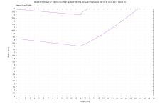
Response in simulator would be cleaner looking with the ring insert as waveguide curve / continuity is better from smaller throat basically. The deeper the throat the narrower coverage the top octave is limited to, because only narrow coverage curve fits. One could make beaming device as well 🙂
Response in simulator would be cleaner looking with the ring insert as waveguide curve / continuity is better from smaller throat basically. The deeper the throat the narrower coverage the top octave is limited to, because only narrow coverage curve fits. One could make beaming device as well 🙂
Here is an internal ring for a DE111 that reduces from r=9.25 to r=8. Does anyone notice problems created by shrinking the exit from 18.5mm to 16mm like this? I can't hear above 12,000Hz, but maybe people who have good hearing can extend high frequency control by shrinking their exit after the phase plug termination.

Throat.Ext.Angle = -5
Throat.Ext.Length = 14
Slot.Length = 0
R-OSSE = {
R = 152 ; horn radius (1/2 diameter)
a = 30.5 ; horn control angle
r0 = 8 ; compression driver throat radius
a0 = 15.25; compression driver exit angle
m = 0.79
r = 0.41
q = 3.4
k = 1.1
b = 0.1
tmax = 1.0
arcterm = 0
}
Attachments

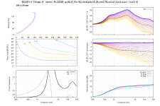
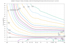
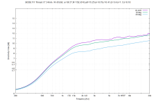
Nice polars. You'll see more when measured with the real driver, whose internals are not a part of the model now. The polars should remain more or less the same but there may be a need for more EQ, as it will probably create some more resonances (as long as they are not very high Q that should not be an issue, IMO).
All this will collapse once the real exit wavefront deviates from flat. I'd guess it won't hold up to 20 kHz with a real driver, but can be close. Definitely I would like to see it.
All this will collapse once the real exit wavefront deviates from flat. I'd guess it won't hold up to 20 kHz with a real driver, but can be close. Definitely I would like to see it.
Last edited:

ATH-DOME
Waveguides for direct radiating tweeters
To not to let it slip through the cracks, this is the waveguide formula presented earlier (with Bliesma T34B):
https://www.desmos.com/calculator/3iswclzjzh
I think it has potential, maybe it could work with other tweeters as well, that would need to be tested (presumably the more rigid dome the better the match to the simulation). Anyone is free to try and use/modify it, just keep the name "ATH-DOME-<size_in_inches>", in this case it would be "ATH-DOME-6".
The nominal coverage is 120 degrees and for that no wave shaping add-ons are needed, the response is still very smooth as a result.

It could easily be made elliptic but there seems to be no advantage, really. This is achieved e.g. by setting the coverage angle to (e.g.) "55 - 15*sin(p)^2" in the script (and of course then simulating it as a full-3D model).
Waveguides for direct radiating tweeters
To not to let it slip through the cracks, this is the waveguide formula presented earlier (with Bliesma T34B):
https://www.desmos.com/calculator/3iswclzjzh
I think it has potential, maybe it could work with other tweeters as well, that would need to be tested (presumably the more rigid dome the better the match to the simulation). Anyone is free to try and use/modify it, just keep the name "ATH-DOME-<size_in_inches>", in this case it would be "ATH-DOME-6".
The nominal coverage is 120 degrees and for that no wave shaping add-ons are needed, the response is still very smooth as a result.
It could easily be made elliptic but there seems to be no advantage, really. This is achieved e.g. by setting the coverage angle to (e.g.) "55 - 15*sin(p)^2" in the script (and of course then simulating it as a full-3D model).
Last edited:
Example, Faital pro hf108, which lists exit angle about 31deg. Measuring by eye from a photo of the driver the conical section depth is perhaps 15mm. Calculating opposing side of right angle triangle with 15mm adjacent side and 15deg angle we get roughly 4mm, so start of the exit section is about 2*4mm smaller in diameter than the 25mm nominal, so roughly 16-20mm depending how accurate the eye was.- I took 16 mm as reachable with some drivers.
Faital pro hf10ak has 21deg exit angle and eye measure of 25mm conical section depth, so about ~4-5mm so again roughly 16-20mm.
Bug screen removal required to get accurate measurement of it 🙂 17mm would be wavelength of ~20kHz
Since hf108 looks to have shallower exit section it enables wider top octave coverage angle with a ring insert than hf10ak, while both could potentially have the top octave "as smooth".
edit. hmm, I wonder if the conical exit is part of the actual motor or could it be machined for even wider exit angle without ill-effects? Machining the nominal exit bigger would accommodate wider coverage waveguide / ring insert. Not sure if anyof it matters too much.
Last edited:
I'd be perhaps more interested in e.g. HF146 (1.4"). With a ring one could get to a ~1" performance (which I still believe is good enough as it is)...

BTW, does anyone know the difference between HF144 and HF146?
BTW, does anyone know the difference between HF144 and HF146?
I have no idea.I wonder if the conical exit is part of the actual motor or could it be machined for even wider exit angle without ill-effects?
Last edited:
Yep, on HF146 the exit section seems to be plastic, so not part of magnet, perhaps detachable and replaceable with a print.
HF201 with even bigger diaphragm looks like has ~1.4" throat available with ring insert, hard to judge by eye. Its titanium dome though. Well, anyway this ring insert stuff is something to consider for some applications.
HF201 with even bigger diaphragm looks like has ~1.4" throat available with ring insert, hard to judge by eye. Its titanium dome though. Well, anyway this ring insert stuff is something to consider for some applications.
That would be great. Can anyone confirm that?on HF146 the exit section seems to be plastic, so not part of magnet, perhaps detachable and replaceable with a print.
(Seems only as a thin sleeve to me.)
Last edited:
Yeah I'm also just looking at the photo, no knowledge on it. By luck its a 2" hole, because:
Comparison datasheet reveals some of the drivers are likely mostly the same: HF141 and HF201 look almost identical in spec and visual, the difference is HF201 has been machiened for 2" exit? = ready for ring insert 🙂 HF141 having 6deg exits angle still, so the throat is wee bit smaller than 1.4", I guess same goes for HF201.

HF146 and HF206 don't seem to have as much common though... perhaps it didn't work out nicely with both sizes and they had to do something quickly, like a plastic part?😀 Hence logic there might be bigger than just a sleeve. HF146 looks nice nevertheless, both visually and paper and has quite small throat and relatively wide coverage available with the ring insert, even if the plastic throat section / sleeve was not detachable.
Comparison datasheet reveals some of the drivers are likely mostly the same: HF141 and HF201 look almost identical in spec and visual, the difference is HF201 has been machiened for 2" exit? = ready for ring insert 🙂 HF141 having 6deg exits angle still, so the throat is wee bit smaller than 1.4", I guess same goes for HF201.
HF146 and HF206 don't seem to have as much common though... perhaps it didn't work out nicely with both sizes and they had to do something quickly, like a plastic part?😀 Hence logic there might be bigger than just a sleeve. HF146 looks nice nevertheless, both visually and paper and has quite small throat and relatively wide coverage available with the ring insert, even if the plastic throat section / sleeve was not detachable.
Last edited:
I think the phase plug termination inside HF146 is still smaller than in HF141/201 but it's hard to tell just from the photos. HF201 would also seem as a good candidate due to the wide exit angle (similar to B&C DE85TN, maybe smoother).
Here on a YT video there seems to be a dent around throat of HF144, from which I could be speculated the plastic throat could actually be that big?🙂

HF144 seems to be quite similar to HF146
edit. HF142 seems to have similar throat as well https://audioxpress.com/article/tes...ession-driver-coupled-with-lth142-60-o50-horn and "visual".
HF144 seems to be quite similar to HF146
edit. HF142 seems to have similar throat as well https://audioxpress.com/article/tes...ession-driver-coupled-with-lth142-60-o50-horn and "visual".
Last edited:
Since its interesting I sent query to their customer service. Lets see if there is an answer 🙂
- Home
- Loudspeakers
- Multi-Way
- Acoustic Horn Design – The Easy Way (Ath4)