Hi mabat,
Kindest regards,
M
I made horns like that; I used a mat board and filled the space in-between with sand....I'm more thinking about bended sheets of metal (per segment), two with some damping layer between. Thick enough to be able to glue them together to make the horn. It's just a simple bending, doable at home.
Kindest regards,
M
With a 1-inch compression driver, is there a way to create a similar dispersion from 15-20 kHz without the very complex phase plug?
https://www.diyaudio.com/community/...ifi-woofer-speaker-builds.352063/post-7346619
https://www.diyaudio.com/community/...ifi-woofer-speaker-builds.352063/post-7346619
I doubt. It seems like ~15k is the reasonable limit with a regular 1" throat. You would have to use some (very) clever trick.
Maybe with a throat insert, making it effectively smaller than 1".
- You really need more of a spherical wavefront to start with to achieve that. Convex dome (if stiff enough), even with its axial motion, is a way to approach that.
Maybe with a throat insert, making it effectively smaller than 1".
- You really need more of a spherical wavefront to start with to achieve that. Convex dome (if stiff enough), even with its axial motion, is a way to approach that.
Last edited:
With a regular 1" throat, this is what I was able to get as "wide controlled directivity"...
(Could be more flat to ~15 kHz but then it would be more abrupt above it.)

The advantage being that one can use such device down to 800 - 1k with dynamics to spare.
(Could be more flat to ~15 kHz but then it would be more abrupt above it.)
The advantage being that one can use such device down to 800 - 1k with dynamics to spare.
Last edited:
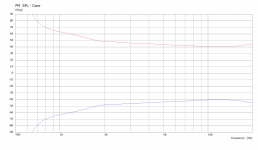
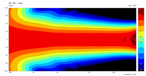
Interesting information about the Purifi approach from the measurement posted by sheeple:
More: https://purifi-audio.com/blog/tech-notes-1/spk16-reference-design-12For starters we use a hard dome that remains pistonic to ultrasonic frequencies.
...
The second being using a ‘Coherer’ i.e., a collection of ring-shaped objects that shape the wavefront around the throat of the wave guide in order to direct energy to the further of axis directions. Finally, the wave guide shape is of course critical for both controlling (ie narrowing) dispersion at the low end of the frequency range and yet allow wide dispersion towards the high frequency range.
...
Interestingly, the optimisation resulted in a waveguide being relatively shallow with a depth of only 16mm (which is surprisingly shallow compared to its 147mm diameter).
I doubt. It seems like ~15k is the reasonable limit with a regular 1" throat. You would have to use some (very) clever trick.
Maybe with a throat insert, making it effectively smaller than 1".
- You really need more of a spherical wavefront to start with to achieve that. Convex dome (if stiff enough), even with its axial motion, is a way to approach that.
Thanks for your answer. If there is nothing to be done with a 1-inch CD, at least design goals are all clear: one’s got to deal with a narrower UHF than rest of the band. Another option is obviously a smaller CD, as in the JBL 708.
There are things that can be done, but they are not without down sides, the Purifi polar graph shows that it is not completely free of them either.If there is nothing to be done with a 1-inch CD, at least design goals are all clear: one’s got to deal with a narrower UHF than rest of the band.
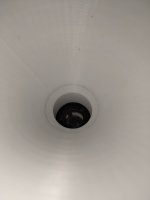
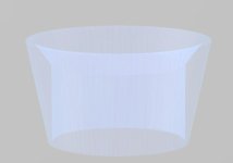
This is not wide coverage but it widens rather than narrows above 15k. It uses an internal ring. With my 3D printer I was able to fit the internal ring snugly inside the DE111 using a 12.002 degree half angle (a cone 25mm diameter 58.8mm in length). I printed the Internal Ring to only 14mm deep to fit inside the DE111 which is 15mm deep, leaving 1mm of wiggle room.
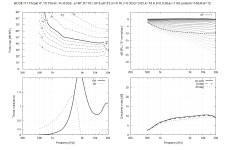
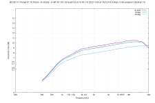
Throat.Ext.Angle = 0
Throat.Ext.Length = 10.75
Slot.Length = 0
R-OSSE = {
R = 101 ; horn radius (1/2 diameter)
a = 46 ;horn control angle
r0 = 9 ; compression driver throat radius
a0 = 23 ; compression driver exit angle
m = 0.76 ;
r = 0.30 ;
q = 3.65 ;
k = 18.6 ;
b = 0.0 ;
tmax = 1.00 ;
arcterm = 160 ;
}
Rot = 12 ; 7


I don't know if you're talking about the one I made for the DE111 or the horns higher up in the thread but mine is only simulation. I haven't finished printing the last part of the horn yet.
Narrowing the aperture which is kind of a diffraction slot, splitting the wavefront and redirecting it, like fins, multi cells and sounds similar to Purifi's coherer rings. Increasing the radiation impedance by bypassing the conical adapter like above isn't quite the same thing.Now I am curious: what is it that you know of, that could be done?
Above 10K greater knowledge of the diaphragm material, phase plug geometry etc is needed to simulate anything accurately. Purifi are using COMSOL multi physics to combine the properties of the driver and the waveguide together which is a step beyond anything ABEC/AKABAK can do.
Here I tried just a smaller throat for my example in #12,384.
This is the regular 1" throat (black line = -6dB):

And this is with 16mm throat (possibly doable with a throat ring?):

It does extend it a bit but still it's not 140deg nominal coverage...
(I don't say it's needed or even a good thing, only that it would be tough to actually achieve that with a 1" compression driver.)
(This is the device from #12,218 shown earlier, designed to be used with an open-baffle midrange.)


This is the regular 1" throat (black line = -6dB):
And this is with 16mm throat (possibly doable with a throat ring?):
It does extend it a bit but still it's not 140deg nominal coverage...
(I don't say it's needed or even a good thing, only that it would be tough to actually achieve that with a 1" compression driver.)
(This is the device from #12,218 shown earlier, designed to be used with an open-baffle midrange.)
Last edited:
Does not narrowing the aperture also change the compression ratio, and hence the driver properties? I like the 16 mm "ring-insert" result from mabat's example. It would make the HF -> UHF transition more even and the sweetspot a bit wider.Narrowing the aperture which is kind of a diffraction slot, splitting the wavefront and redirecting it, like fins, multi cells and sounds similar to Purifi's coherer rings.
^^ Depends on the throat depth of the driver. My driver has conical exit starting about 16mm diameter to 1" at exit, about 1" deep. I played with the throat/ring insert so that R-OSSE profile started right at the 16mm start and the top octave smoothens out in simulator, but cannot get coverage angle past 90deg or so if I remember. The throat is just too deep for smooth profile with wide coverage. Perhaps some more optimization could make it, but this is the impression I remember from the experiments. We would need compression driver with small opening and no / short conical exit.
Perhaps if the ring insert was straight tube without any expansion could work for some driver. Or driver with 0deg exit angle, or some big exit angle.
Perhaps if the ring insert was straight tube without any expansion could work for some driver. Or driver with 0deg exit angle, or some big exit angle.
Last edited:
The throat insert can only help, it improves on everything if done right (*). There's really no drawback other than making the waveguide to one specific driver.
(*) If possible, it shouldn't be a tube (or only as short as absolutely necessary to reach the desired coverage angle). Tube will cause resonances (the same way as the original conical section does), correctable on a signal level for the most part, but still.
(*) If possible, it shouldn't be a tube (or only as short as absolutely necessary to reach the desired coverage angle). Tube will cause resonances (the same way as the original conical section does), correctable on a signal level for the most part, but still.
Last edited:
...But maybe this is far more interesting for 1.4" or 2" drivers (especially for those with wide exit angles).
This can be used to design a throat ring (a Desmos graph): https://www.desmos.com/calculator/qkhbbse7c1
Last edited:
I was just asking the above question as I mean to remember from some reviews of compression drivers, or speakers that use compression drivers, that technically versed reviewers sometimes highlighted the compression ratio as a performance criterion in HiFi. Lesser was assumed to produce less distortion.
So lets take the Celestion CDX1-1747 1-inch compression driver as an example. I do not know the chamber diameter itself, so as a starter, I will simply use the voice coil versus aperture ratio instead:
44 mm/25 mm = 1.76
44 mm/16 mm = 2.75
This is a significant difference and I wonder if someone knows how this 150 percent increase in compression ratio would affect sound.
But that's not a compression ratio in a CD. For that you would have to relate the (projected) diaphragm area to the total phase plug slits area where it connects the diaphragm chamber. That's not changed in any way (and would be more like 10 : 1 for most drivers).
What changes is the overall expansion rate but there's no "right" expansion anyway.
- The whole idea behind the ring insert is that the more you do to the wavefront when the dimensions of the surrounding duct are still small, the better. Note that the included angle of the walls at the exit of the ring is considerably wider than with the original exit, at the same diameter. That's what counts...
Ideally, the whole ring and the WG should form a single smooth curve, e.g. one single R-OSSE profile. Then the only place of a possible wavefront curvature (expansion) mismatch will be where the ring starts, i.e. typically at a noticeably smaller diameter than the exit of the driver.
Last edited:
- Home
- Loudspeakers
- Multi-Way
- Acoustic Horn Design – The Easy Way (Ath4)