Kind of unrelated, but I asked chat GPT to write software that output a biradial horn flare curve. [...]
# Calculate the flare rate coefficient
k = math.tan(exit_angle) / throat_radius
# Calculate the corresponding radius values
r = throat_radius * np.sqrt(1 + (k * x)**2)
The quoted formula represents a simple (infinite) OS contour.
I'm not sure about the rest - the mentioned cutoff frequency and radius, I doubt it has any sensible use.
Last edited:
I'm having another minor issue that using the import curves script in fusion 360 is resulting in a horn of 10x the size of the modeled horn. This is easy to fix by just scaling the sketch.
The .afp file contains unitless data in mm. The script multiplies that with 0.1, so you end up with implicit cm. cm is the default for Fusion 360.
Have you changed the default by any chance?
Ps. I will check if I can make my script more explicit.
Have you changed the default by any chance?
Ps. I will check if I can make my script more explicit.
If you used Grid Export include Scale = 0.1 fusion likes to default to cm.I'm having another minor issue that using the import curves script in fusion 360 is resulting in a horn of 10x the size of the modeled horn. This is easy to fix by just scaling the sketch.
GridExport:f360 = {
ExportProfiles = 0
ExportSlices = 1
Scale = 0.1
}
I'm (still) having problems with fields. I've started ABEC3 in windows 8 compatibility mode (on win11 machine), but this still doesn't look right:
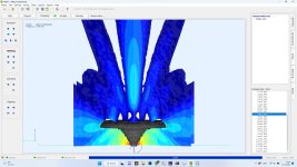
Higher SPL on the back...
Anyone any idea what is going on and how to fix that?
Here is the ath file, btw:

Higher SPL on the back...
Anyone any idea what is going on and how to fix that?
Here is the ath file, btw:
Code:
R-OSSE = {
  R = 225 ; increasing nr 2
  a = 30
  r0 = 12.7
  a0 = 15.5
  k = 1.2984
  r = 0.5124
  m = 0.806909
  b = 0.31678
  q = 2.9633
}

Mesh.LengthSegments = 40
Mesh.AngularSegments = 64

Mesh.SubdomainSlices =

Mesh.ThroatResolution = 4
Mesh.MouthResolution = 8
Mesh.InterfaceResolution = 5
Mesh.RearResolution = 15

Source.Shape = 1

ABEC.SimType = 2
ABEC.MeshFrequency = 1000
ABEC.NumFrequencies = 40
ABEC.Abscissa = 1
ABEC.f1 = 200
ABEC.f2 = 20000

ABEC.Polars:SPL_H = {
  MapAngleRange = 0,180,37
  NormAngle = 0
  Distance = 1.5
}

ABEC.Polars:SPL_V = {
  MapAngleRange = 0,180,37
  NormAngle = 0
  Inclination = 90
  Distance = 1.5
}

;ABEC.SphericalField:1 = {
;  Radius = 0.5
;}

ABEC.AxialField:1 = {
  Inclination = 60 ; [deg]
  Radius = 0.4 ; [m]
  z0 = 0.0 ; [m]
  z1 = 0.75 ; [m]
  Resolution = 10,20,50,30 ; [mm]
}

Output.ABECProject = 1
Output.STL = 1

Report = {
  Title = ST260BLD
  PolarData = SPL_H
  ;Width = 1200
  ;Height = 900
}No clue. I can only report that using your script on my setup (Win10) works without problems.


(I reduced the resolution a bit to speed it up.)
(I reduced the resolution a bit to speed it up.)
Last edited:
For an axisymmetric horn there's of course no need to do it with a full 3D mesh.
In a CircSim mode (ABEC.SimProfile = 0), to add a field insert something like this into observation.txt:


- BTW, this is the same waveguide solved as a full-3D mesh (~2700 elements) and in CircSym mode:


In a CircSim mode (ABEC.SimProfile = 0), to add a field insert something like this into observation.txt:
Code:
Nodes "FNodes"
  Scale=1m
  1  0.0 0.5
  2  0.7 0.5

Field "Field_1"
  RefNodes="FNodes";
  MeshFrequency=8kHz
  AnalysisType=Pressure; BodeType=LeveldB; StepSize=3; Range=48;
  Alpha=0.9
  601  1 2
- BTW, this is the same waveguide solved as a full-3D mesh (~2700 elements) and in CircSym mode:
nope, also rubbish.Did the spectrum solve and display correctly?
Then ABEC itself is the issue not how the fields were created.nope, also rubbish.
ABEC in later versions of Windows seems to be unstable, changes to compatibility mode and changing the NUC settings and restarting have worked. I find it is handy to check something quick to see if it solves properly before wasting time on generating rubbish.
Thanks, configuring the observations file directly worked. I looks like I had tried that myself sometime, but I didn't succeeded back then.
Too bad ABEC3 and windows 11 don't seem to come along very well. I was trying to model an enclosure + free standing waveguide...
Too bad ABEC3 and windows 11 don't seem to come along very well. I was trying to model an enclosure + free standing waveguide...
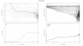
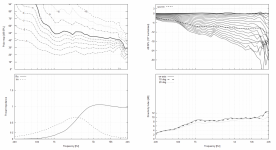
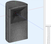
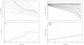
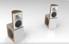
Iteration of my shaped cabinet with "WG v.4 - The Rising DI"
Linear DI +4dB 1k to 10k
Charts are wg in cabinet only - no LFSource
1st watt friendly design
Initial look - 10 points with following settings. Running 40 points over night.
Linear DI +4dB 1k to 10k
Charts are wg in cabinet only - no LFSource
1st watt friendly design
Initial look - 10 points with following settings. Running 40 points over night.
Code:
Mesh.AngularSegments = 100
Mesh.LengthSegments = 24
Mesh.CornerSegments = 5
Mesh.ThroatResolution = 2.5 ; [mm]
Mesh.MouthResolution = 7.0 ; [mm]
Mesh.InterfaceResolution = 7.0 ; [mm]

Last edited:
I see 8 points, linearly spaced between 200-16000 Hz, i.e. with 2257 Hz step between them. This is way too low, as there's almost no data below 5 kHz.
- One feasible option is to reduce the mesh resolution considerably and repeat the calculation for the lower (<5k?) band only, with a higher number of points and with log step.
- One feasible option is to reduce the mesh resolution considerably and repeat the calculation for the lower (<5k?) band only, with a higher number of points and with log step.
Last edited:
With two points the result is always linear 😉
With 40 points wiggles are starting to appear.
With 40 points wiggles are starting to appear.
Wiggles always appear with baffles 😀 or perhaps
Wiggles always appear with physical objects.
Wiggles always appear with physical objects.
These are still nice results 👍
- Home
- Loudspeakers
- Multi-Way
- Acoustic Horn Design – The Easy Way (Ath4)
