Oh, wow. That's quite interesting. Conventional tech would have that being made on a CNC lathe. I wonder what the cost difference is.Mabat, as someone working with with large scale additive i came across this post and I'm simply too curious: is this your waveguide?
No, nothing I would be aware of. Looks familiar for sure. How large is it?Mabat, as someone working with with large scale additive i came across this post and I'm simply too curious: is this your waveguide?
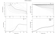
That's not a good approach. It will make the DI more steep towards high frequencies as a result. To make the DI lower, keep the size but make the wall angle simply more open.You can scale down the ST-260 to reduce DI around 1kHz.
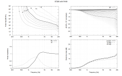
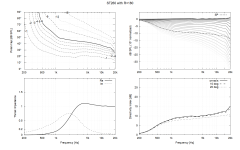
Would it matter? Both loudspeaker systems would undergo change of DI from 0 to ~12db and the difference is around the crossover, smoother transition instead of stair step. You are right though, angle of the DI slope would be bit deeper if just scaled down. Maintaining the same angle of DI slope between 1kHz - 10kHz would need shallower device.
Here is ST260 scaled down to ST180 🙂


edit. and up to ST360

Here is ST260 scaled down to ST180 🙂


edit. and up to ST360

Last edited:
following the path of least resistance, my first try I'm increasing the ROSSE coverage angle parameter
Its more than that though. looking at the CD only response, the H polar map is a flat bar. if I increase coverage angle the right amount, I will get a flat bar equal in width to that of the almost flat woofer bar
Its more than that though. looking at the CD only response, the H polar map is a flat bar. if I increase coverage angle the right amount, I will get a flat bar equal in width to that of the almost flat woofer bar
I also showed some wider variants around these posts here:
https://www.diyaudio.com/community/...-design-the-easy-way-ath4.338806/post-7221053
https://www.diyaudio.com/community/...-design-the-easy-way-ath4.338806/post-7221655
https://www.diyaudio.com/community/...-design-the-easy-way-ath4.338806/post-7221053
https://www.diyaudio.com/community/...-design-the-easy-way-ath4.338806/post-7221655
Yeah lower DI waveguides can be found with the power in the ATH.
I can understand the appeal of ST260, it is very convenient as you have published it and it has reports sounding good, STL files and all, suitable for many systems right away 🙂 Wanted to point out just scaling it is quite easy task.
I can understand the appeal of ST260, it is very convenient as you have published it and it has reports sounding good, STL files and all, suitable for many systems right away 🙂 Wanted to point out just scaling it is quite easy task.
Basic STLs for the wider versions are here: https://www.diyaudio.com/community/...-design-the-easy-way-ath4.338806/post-7219991
- Including the 220 mm version, which may be adequate.
But today, with the help of Ath and Fusion 360, it's a matter of minutes to prepare such (customized) models.
- Including the 220 mm version, which may be adequate.
But today, with the help of Ath and Fusion 360, it's a matter of minutes to prepare such (customized) models.
I can see its not going to be that easy. time out while I go back to what I should be doing instead of playing here
I believe the bed they use is around 1100mm wide and around 2000mm long, so fairly large it would seem.No, nothing I would be aware of. Looks familiar for sure. How large is it?
https://www.linkedin.com/posts/cead...49579552768-lJUM?trk=public_profile_like_view
"Innovative large scale 3d printed horn with unique curvatures for optimal sound qualities"
- Hmm, wondering what that could be 🙂
"Innovative large scale 3d printed horn with unique curvatures for optimal sound qualities"
- Hmm, wondering what that could be 🙂
Well, that all depends. Besides the initial cost of the setup, the print costs are not too different from normal FDM. You can use simple and cheap slicer sofware or very advanced multi-axis sofware depending on your needs, but in the end it is just a post processor generating robot codes and a robot arm moving.Oh, wow. That's quite interesting. Conventional tech would have that being made on a CNC lathe. I wonder what the cost difference is.
Hmm... https://www.additaudio.com/https://www.linkedin.com/posts/cead...49579552768-lJUM?trk=public_profile_like_view
"Innovative large scale 3d printed horn with unique curvatures for optimal sound qualities"
- Hmm, wondering what that could be 🙂
Measuring the exit wavefront shape (again) -
This has occured to me last night, I don't know if it can be of any help, but nevertheless - I made this jig that has a flush-mounted electret mic that can move freely from the center of the aperture to its edge - the mic is in a wall that closes the driver. I thought the trick might be in time gating. The gate is obviously very short but as the frequencies of interest are quite high, I also reasoned this doesn't have to be a big problem.
Can this lead somewhere?


This is the Faital HF1440 (1.4"), FR and IR 0, 5 and 10 mm off the center (96 kHz sampling, time window indicated):

IR zoomed-in (perhaps even the curvature could be directly estimated from the delays?):

This has occured to me last night, I don't know if it can be of any help, but nevertheless - I made this jig that has a flush-mounted electret mic that can move freely from the center of the aperture to its edge - the mic is in a wall that closes the driver. I thought the trick might be in time gating. The gate is obviously very short but as the frequencies of interest are quite high, I also reasoned this doesn't have to be a big problem.
Can this lead somewhere?
This is the Faital HF1440 (1.4"), FR and IR 0, 5 and 10 mm off the center (96 kHz sampling, time window indicated):
IR zoomed-in (perhaps even the curvature could be directly estimated from the delays?):
"Can this lead somewhere?"
Would that be good for measuring the wavefront of a Paraline lens? Help determine where to place your input hole and/or change the parabola width to height ratio.
Would that be good for measuring the wavefront of a Paraline lens? Help determine where to place your input hole and/or change the parabola width to height ratio.
5, 10, 15mm off the center (176.4 kHz sampling, yet a bit shorter time window):

0 (blue) and 15 mm:

At 12.8 kHz the difference between the center and the edge would be ~5 dB. It that possible?
0 (blue) and 15 mm:
At 12.8 kHz the difference between the center and the edge would be ~5 dB. It that possible?
well I stole some time and ran several iterations. The 220 was marginally better than the 260 but not a perfect match. I tried increasing the coverage angle parameter from 39 degrees to 50 degrees and that would have been even better except for some narrowing that was introduced between 1 and 2 khz. If anyone has any idea which ROSSE parameter is most likely to have an effect on this, please let me know.I can see its not going to be that easy. time out while I go back to what I should be doing instead of playing here
Otherwise, I am going to stop here because I don't have real woofer directivity, just synthesized directivity using Vituix diffraction tool. I need to improve on that before I go further on the waveguide.
I think that there is promise.
The issue that I might have is: the need for correcting for the fact that the loading is not normal for either the mic or the driver. The theory says however that as long as the wavelengths are bigger than the enclosed chamber the more the pressure directly follows the source. So up to some frequency it should work if you can resolve the times of arrival differences in the signals based almost exclusively on first transient arrival.
The issue that I might have is: the need for correcting for the fact that the loading is not normal for either the mic or the driver. The theory says however that as long as the wavelengths are bigger than the enclosed chamber the more the pressure directly follows the source. So up to some frequency it should work if you can resolve the times of arrival differences in the signals based almost exclusively on first transient arrival.
- Home
- Loudspeakers
- Multi-Way
- Acoustic Horn Design – The Easy Way (Ath4)