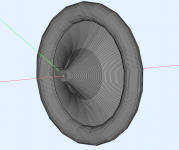
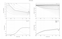
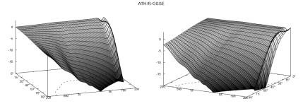
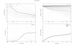
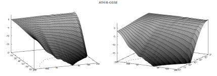
It may have some (unknown) limitations at the moment but in general it seems to work: https://at-horns.eu/ext/ath-4.9.0-pre-230109.zipmabat, would it be possible to enter a set of [x,y] coordinates in the ath waveguide config file? Or a reference to another file? That would give me a lot more freedom and you wouldn't have to process my wild ideas.
Simply define a line like the following one in your script (file path can be relative to the ATH directory or absolute).
Profile = D:\temp\coords.txt
The file should contain a space-separated pair of X Y coordinates per line ([mm]).
Last edited:
Not yet. I would have told you 🙂
- Don't take this as some "new release", it's really just a quick&dirty try to help to speed up the experiments which I find most interesting.
- Don't take this as some "new release", it's really just a quick&dirty try to help to speed up the experiments which I find most interesting.
Last edited:
You can provide a coordinates file 🙂Is there the new back side definition functionality on this pre release?🙂
The drawing/model itself doesn't seem to be wrong. It uses the "mathematical" back side (Mesh.RearShape=2) which is a possible trick how to avoid modeling the whole back. I used that occasionally but it's not as accurate as a full model. (I only don't see the source elements (?)).running maiky's code through Ath 4.9 gives me a very weird drawing which won't solve the issue for me either
I have this as coords.txt:
and I get lots of:
Do I need to enter just e.g. the R-OSSE coordinates, or do I also have to provide the back side of the shape?
Code:
0.000000 12.700000
7.623634 15.777872
15.121538 19.658011
22.489087 24.025319
29.721288 28.706582
36.812750 33.609098
43.757652 38.682485
50.549708 43.898674
57.182131 49.241595
63.647598 54.701697
...
and I get lots of:
Code:
Warning : Start point 2 and end point 10 of GEO line 3 are closer than the geometrical tolerance, at position (0, 0, 0)
Warning : Start point 2 and end point 3 of GEO line 4 are closer than the geometrical tolerance, at position (0, 0, 0)
Warning : Start point 3 and end point 11 of GEO line 5 are closer than the geometrical tolerance, at position (0, 0, 0)
Warning : Start point 3 and end point 4 of GEO line 6 are closer than the geometrical tolerance, at position (0, 0, 0)
Warning : Start point 4 and end point 12 of GEO line 7 are closer than the geometrical tolerance, at position (-0, 0, 0)
....
Do I need to enter just e.g. the R-OSSE coordinates, or do I also have to provide the back side of the shape?
Try to disable the STL output (Output.STL = 0).and I get lots of: ...
Just the profile curve (as you see e.g. in Desmos). The back side and everything else is then calculated/processed as usual. That's the idea.Do I need to enter just e.g. the R-OSSE coordinates, or do I also have to provide the back side of the shape?
Which means you should not create a closed surface yet, like a sphere. That will require some additional logic in the software. Keep it open at the back (curiously, it also seems to solve better that way).
Looking good! (It did already before). Why don't you get rid of the hole above 15k? (You have probably Source.Shape=2 or something like that).
- BTW, in that latest release there's a new parameter arcterm inside the R-OSSE definition doing just that. You can set it to e.g. 270 [deg].
- BTW, in that latest release there's a new parameter arcterm inside the R-OSSE definition doing just that. You can set it to e.g. 270 [deg].
I did try something with the source shape as you mentioned it before. I can't get it to work... I have Shape=1 btw.
Ath says: -matched wavefront radius: 47.523 mm
Ath says: -matched wavefront radius: 47.523 mm
Hmm, I have never seen that. OK, I don't know then 🙂
Something must be different near the throat or with the source.
Something must be different near the throat or with the source.
Last edited:
It seems that the larger the waveguide, the easier it is to get rid of the HF diffractions without affecting the DI at lower frequencies (too much). The above is already just brilliant.
- Let us know then at what SPL you hear a difference 🙂
- Let us know then at what SPL you hear a difference 🙂
I mixed thinks up a bit. Ath seems to chose spherical/flat wavefront on its own. That does alter the peak >15kHz. It also seems to introduce the anomaly at lower frequency and higher angles.
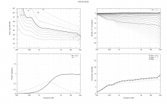
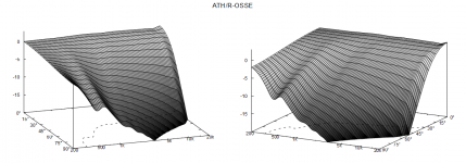
So, does that mean that the bump is dependent on the wavefront type (spherical/flat)? I don't know what my driver has.
p.s. Changed k from 1.2984 to 1 also in this graph, but have seen it happen without also.


So, does that mean that the bump is dependent on the wavefront type (spherical/flat)? I don't know what my driver has.
I can hear it already!- Let us know then at what SPL you hear a difference 🙂
p.s. Changed k from 1.2984 to 1 also in this graph, but have seen it happen without also.
That's hard to believe but maybe you have something in your script that mixes that up. The on-axis hole definitely emerges with a flat wavefront as the source.Ath seems to chose spherical/flat wavefront on its own.
Yea, I get the same DI bump around 500 Hz when I define the arc termination with arcterm=270. The overall shape looks quite the same to what you have but obviously something is different. The value of t at the junction (max curvature) in my case is ~0.922 and the arc radius is 30.3 mm with the center at [107.73; 194.56]. I used k=1.2984.
Last edited:
Yeah that low frequency DI hump is sound around the device, clearly visible now when diffraction backwave is eliminated with the midsized roundover on the lip. To get rid of this the roundover needs to be big like demonstrated earlier, it has to increase path length around the whole device. The whole thing needs to be shaped closer to a sphere than a mushroom to get rid of it.
The other option is to make smaller roundover on the lip to cure only the HF diffraction and leave LF main diffraction backwave be, which balances out this LF DI hump which is on passband because path length around the device at 500Hz is too short, the device is too small (depthwise) 😉
The other option is to make smaller roundover on the lip to cure only the HF diffraction and leave LF main diffraction backwave be, which balances out this LF DI hump which is on passband because path length around the device at 500Hz is too short, the device is too small (depthwise) 😉
No, I don't think that's related.So, does that mean that the bump is dependent on the wavefront type (spherical/flat)?
Nobody knows what their driver has. Probably the best what you can hope for is a spherical wave corresponding to the exit angle (i.e. set Source.Shape = 1).I don't know what my driver has.
- Home
- Loudspeakers
- Multi-Way
- Acoustic Horn Design – The Easy Way (Ath4)
