
In a way, it works.The next one.
So we need a more gradual "letting go" of the sound wave as it hits the edge (which is what is really feels like if you are a sound wave).
Both projects created by ath and the ABEC3 one you posted here result in very weird outcomes. No idea what is wrong...The rest is on you guys
No, just new at the horn construction bit. I’m a woodworker and would love to turn or carve some beautiful bubinga horns or waveguides. At least horn design is founded in science, not like those infinite baffle thingies. Woops. 😁 I will read the thread, so much to learn. The title just struck my funny bone, here’s the easy way… 500 posts later you guys are still working on it. Anyway, I’m glad that people like you are still at it and people like me can learn (and make) new things every day.Or maybe you haven't paid attention 🙂
Ath is a really easy way to design a horn. Get the software working (not easy for everyone) put some values in a configuration file and hit go.I will read the thread, so much to learn. The title just struck my funny bone, here’s the easy way… 500 posts later you guys are still working on it.
The hard part and the reason for 11,000+ posts is deciding what is possible and what works best. There is never likely to be complete agreement on those points which causes the discussion to continue.
Does anyone here have the diaphragm & surround dimensions for: Scanspeak 6640 or SB/Satori Be or TX tweeters? Also, anyone try to model and AMT and horn?
Strange, it works on my PC perfectly.Both projects created by ath and the ABEC3 one you posted here result in very weird outcomes. No idea what is wrong...
Probably pebcak...
Because I'm unable to simulate it myself, I'll drop it here:
What about varying the curvature of the waveguide around t=1? Maybe it is more gradual than a varying hard edge.
Because I'm unable to simulate it myself, I'll drop it here:
What about varying the curvature of the waveguide around t=1? Maybe it is more gradual than a varying hard edge.
You can vary all the R-OSSE parameters using 'p' as in the tmax example above (p is the angle around the horn). That way you can create a device with varying anything.
The easiest is to take two profiles, between which you let the shape alternate smoothly - all parameters can be changing at the same time.
If the two profiles have the value of some parameter v0 and v1, simply set <parameter> = v0 + (v1-v0)*sin(f*p)^n. You can set frequency of the transition with 'f' (how many times it happens around the horn (=2f)). The value 'n' set the "shape" of the transition and should be an even integer, 2 being a simple sinusoid.
Last edited:
Oh, I wouldn't want to do that myself 🙂I will read the thread, so much to learn.
You can just read the current report: https://at-horns.eu/release/R-OSSE Waveguide rev7.pdf
(It's addressing the axisymmetric horns only. It's possible to desing rectangular horns (made of boards) as well but there's no summary for that yet).
Last edited:
Had the same problem, same as the BLD script...Probably pebcak...
Because I'm unable to simulate it myself, I'll drop it here:
What about varying the curvature of the waveguide around t=1? Maybe it is more gradual than a varying hard edge.
Code:
R-OSSE = {
R = 130.0
r0 = 12.7
a0 = 7.5
a = 39
k = 1.8
r = 0.3
b = 0.3
m = 0.8
q = 3.7
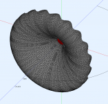
tmax = 0.95 + 0.1*sin(10*p)^2
}
Source.Shape = 1
; -------------------------------------------------------
; Mesh Settings
; -------------------------------------------------------
Mesh.LengthSegments = 36
Mesh.AngularSegments = 48
Mesh.ThroatResolution = 5 ; 10
Mesh.MouthResolution = 12 ; 16
Mesh.RearResolution = 15 ; 25
Mesh.WallThickness = 5
Mesh.SubdomainSlices = 35
Mesh.InterfaceOffset = 25
Mesh.InterfaceDraw = 0
Mesh.RearShape = 2
; -------------------------------------------------------
; ABEC Project Settings
; -------------------------------------------------------
ABEC.SimType = 2
ABEC.MeshFrequency = 1000 ; [Hz]
ABEC.f1 = 500 ; [Hz]
ABEC.f2 = 12000 ; [Hz]
ABEC.NumFrequencies = 54
ABEC.Abscissa = 1
ABEC.Polars:SPL_H = {
MapAngleRange = 0,180,37 ; 5deg resolution
}
ABEC.Polars:SPL_V = {
MapAngleRange = 0,180,37 ; 5deg resolution
Inclination = 90 ; [deg]
}
; -------------------------------------------------------
; Output
; -------------------------------------------------------
Report = {
Title = "Athcfg2try"
NormAngle = 0 ; [deg]
MaxAngle = 180 ; [deg]
DrvImp_Range = 10
Width = 1024
Height = 768
GnuplotCode = 3x2n.gpl
}
Output.SubDir = "test"
Output.STL = 0
Output.ABECProject = 1That should work
At least the frequency vector is wrong on mine for some reasons...
I've obviously changed that for the above picture.
I don't have a clue what the problem is. I tried to calculate it again with NUC on (it was off previously) and I still get the same clean results.
I don't have a clue what the problem is. I tried to calculate it again with NUC on (it was off previously) and I still get the same clean results.
I get almost the exact same rubbish when I try and solve it, running maiky's code through Ath 4.9 gives me a very weird drawing which won't solve the issue for me either. The output from solving is based on mabat's project which does look correct in the drawing.


- Home
- Loudspeakers
- Multi-Way
- Acoustic Horn Design – The Easy Way (Ath4)