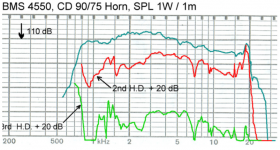
The wobble is definitely a resonance - stored energy, not a reflection or diffraction. You can recognize resonance by a constant oscillation period in the impulse response. The other effects don't behave like that.
Last edited:
Looks like the polarity is inverted somewhere in the chain, on a single driver in phase the peak should go up first 🙂
It's just 1 mic and 1 CD
The wobble is definitely a resonance - stored energy, not a reflection or diffraction. You can recognize resonance by a constant oscillation period in the impulse response. The other effects don't behave like that.
Could be the 3d print resonates 🙂
I'll try to hit it with something and record to see if it resonates 😀
Based on the IR plot it's a resonance around 17 - 18 kHz, it's hardly the waveguide. It comes from the driver, IMHO.
If you correct this with a simple passive RLC (or a DSP biquad, doesn't matter) you should get rid of it to a large degree. (I'm not sure I would bother this high in frequency but you can always test audibility of this easily.)
If you correct this with a simple passive RLC (or a DSP biquad, doesn't matter) you should get rid of it to a large degree. (I'm not sure I would bother this high in frequency but you can always test audibility of this easily.)
Last edited:
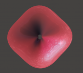
For the next release of Ath I implemented a new parameter/feature: Slot.Length
It basically adds a flat segment before the actual OS-SE profile, of which the length can be continuously variable (along with all the other parameters). It will be fun watchig what people come up with 🙂
It basically adds a flat segment before the actual OS-SE profile, of which the length can be continuously variable (along with all the other parameters). It will be fun watchig what people come up with 🙂
Attachments
The wobble is definitely a resonance - stored energy, not a reflection or diffraction. You can recognize resonance by a constant oscillation period in the impulse response. The other effects don't behave like that.
That makes sense as the BMS4550 has a pretty nasty breakup at 18K, there looked to be diffractive ripple in the FR which is what my comment was based on.
Attachments
For the next release of Ath I implemented a new parameter/feature: Slot.Length
It basically adds a flat segment before the actual OS-SE profile, of which the length can be continuously variable (along with all the other parameters). It will be fun watchig what people come up with 🙂
Wow! and I agree....I was just swallowing Patricks post and staring at my 2380a lol....I wrote a response and had to delete it cause it finally sank in lol... thinking about the discussions surrounding the 2380a I've had in the past...the idea of its error in technicality (dispersions slots and distortion) combined with the 2382a being used on the Strauss mastering monitor...for home spl levels...maybe there is some potential to combine loading and constant directivity that we have left on the table? Especially after cleaning up the sharp edges.
I envision a focus on slot modelling as a separate discussion from the rest of the horn flair? In that maybe one could take an ideal constant directivity slot and add it to a number if different flare profiles...
One thing to take into account is the idea that with this 2380a the exits area is 3.1416"...an somewhat rough measurement of the slots ending shows the CSA to be ~4.25 (1" wide and 4.25" tall) and with a 4.5inch dept....its sorta like a truncated horn .....that has a very narrow width, thus losing direcivity on the horizontal plane (at HF)...into... another horn/waveguide profile, to help clean things up...at least thats how I see it...
Last edited:
Frankly, I don't believe it will happen. I also don't quite agree with what Patrick Bateman wrote above....maybe there is some potential to combine loading and constant directivity that we have left on the table?
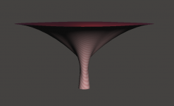
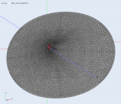
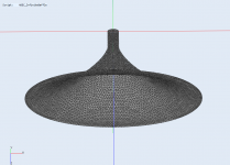
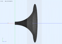
Attached is a STL file for an extremely simple example -
Throat.Diameter = 36
Length = 200
Coverage.Angle = 45 + (14-45)*sin(p)^2
OS.k = 1 + (2.2-1)*sin(p)^2
Slot.Length = 60 + (2-60)*sin(p)^2
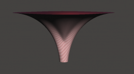
Throat.Diameter = 36
Length = 200
Coverage.Angle = 45 + (14-45)*sin(p)^2
OS.k = 1 + (2.2-1)*sin(p)^2
Slot.Length = 60 + (2-60)*sin(p)^2
Attachments

Last edited:
Maybe have a read of this paper from Keele, describes pretty much what you are but back in 1975 😉maybe there is some potential to combine loading and constant directivity that we have left on the table? Especially after cleaning up the sharp edges.
http://www.xlrtechs.com/dbkeele.com/PDF/Keele%20(1975-05%20AES%20Preprint)%20-%20Whats%20So%20Sacred%20Exp%20Horns.pdf
The BEM results for infinite baffle (1.4" throat, waveguide is 495 x 385 x 200 mm) -Attached is a STL file for an extremely simple example ...
Attachments
And a bit larger - 578 x 464 x 240 mm (W x H x D).

Attachments
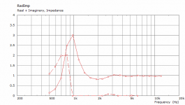
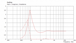
The impedance peak can be reduced considerably by further tweaking, if considered a bad thing, which it maybe isn't.
wouldn't the impedance peak matter less based on x-over point and type....
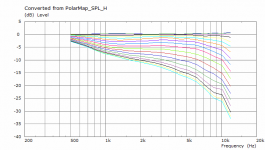
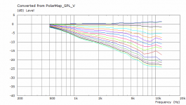
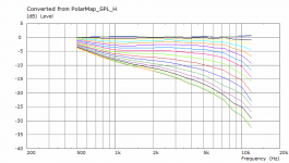
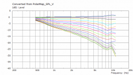
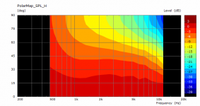
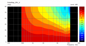
and unless i can't interpret polar charts well how is it that a fifteen degree window across the bandwidth is acceptable....
and unless i can't interpret polar charts well how is it that a fifteen degree window across the bandwidth is acceptable....
Last edited:
The wobble is definitely a resonance - stored energy, not a reflection or diffraction. You can recognize resonance by a constant oscillation period in the impulse response. The other effects don't behave like that.
Those minor wobbles indeed correspond to break-up resonances, typical of all 455.. drivers. Nothing to worry about imo.
I bet many people even appreciate the added sparkle, even though it isn't true to the original signal.
Last edited:
That makes sense as the BMS4550 has a pretty nasty breakup at 18K, there looked to be diffractive ripple in the FR which is what my comment was based on.
My niece (8 years old) could be bothered by it.
For the next release of Ath I implemented a new parameter/feature: Slot.Length
It basically adds a flat segment before the actual OS-SE profile, of which the length can be continuously variable (along with all the other parameters). It will be fun watchig what people come up with 🙂
Thanks for including this feature.
Over the last 50 years (starting with Abraham Cohen) research has been published regarding diffraction slots. There's specific math involved regarding wavefront propagation along the horn, versus optimal slot length/width/height, versus (eventual) constriction factor in relation to throat and mouth size.
Some clues are given in Keele's horn papers, but there's a lot more available.
Unfortunately, I am currently unable to access the data.
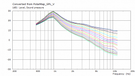
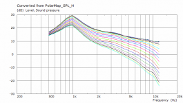
The nominal beam width is usually given at the -6dB point which on these charts is the outer edge of the orange band, on the Horizontal graph above at 5K the beam width is wider than 90 degrees as the graph is only half the beam width. The slope of the beam as it moves above the on axis rises showing the directivity rising with frequency.and unless i can't interpret polar charts well how is it that a fifteen degree window across the bandwidth is acceptable....
- Home
- Loudspeakers
- Multi-Way
- Acoustic Horn Design – The Easy Way (Ath4)