Yes I feel the same, that it is better to stay spherical, and use some ceiling absorption if needed.I can only say that the best results I ever obtained were with circular mouths. It may be partly because axisymmetric is so easy to work with, but at least it's definitely not an obstacle preventing perfect results. You would have to have a very good reason for a non-circular shape to begin with, IMHO. Based on my experience, you will lose some of the pristine quality but you may gain something else (just can't imagine at the moment what it could be).
Yes"under a 1/4 up to 1/2 a wavelength" is that = under 1/2 wl?
As rough rules of thumb go yes. 0.5 to 0.7 wavelengths is the area best avoided if overall power response and DI smoothness is a goal.1/4 <-> 1/2
1 <-> 1.4
is OK?
//
I assume you are talking about Kimmo's guidelines on driver spacing? Do you have a link to these please..
This page and the ones around it have some worked examples
VituixCAD
This thread at ASR has some relevant info too this post from Tom Danley highlights the issue that can present at 0.5 wavelength.
Crossover filter - Effects on the vertical radiation | Page 2 | Audio Science Review (ASR) Forum
Another one here
VituixCAD v2 - Page 6
VituixCAD
This thread at ASR has some relevant info too this post from Tom Danley highlights the issue that can present at 0.5 wavelength.
Crossover filter - Effects on the vertical radiation | Page 2 | Audio Science Review (ASR) Forum
Another one here
VituixCAD v2 - Page 6
Last edited:
You could flair the cosmetic rim on the woofer like I did in that photo. It's not obvious, but there isn't a discontinuity at the junction.Is there a way to model the response when a freestanding axisymmetrical waveguide is “interrupted” when the axisymmetry is “carved into” to decrease the center-to-center spacing? Though the attached shows a baffle-mounted waveguide, the image should suffice for clarification
Thanks for bring this up. It would be a nice challenge in integrate this kind of horn into a speaker. Is there a spreadsheet out there that calculates this? I would be interested in matching one to a specific driver.What about JLMC Iwata? Can it be modelled too?
How do I have to interpret cut-off frequency for a waveguide with an ath report? This is a report for a waveguide with a diameter of 315 mm, baffle-mounted. If I use the -3 dB polar as a guideline, it looses pattern control already at 2 kHz, making a 1.25 kHz xo-point infeasible. I was not expecting this due to the good size and to me, there are three possible explanations:
1) because of the extended termination in comparison to many similar sized commercial waveguides, pattern control is actually lesser.
2) the widening of the pattern is also present with similar sized commercial waveguides with which the diy scene has gathered experiences before, but is usually mitigated by the reduction of SPL by a crossover point that is slightly below the widening
3) Actually, the -3dB polar pattern is not that strict. The ankle where it shoots up is not most important.


Can you help me out?
1) because of the extended termination in comparison to many similar sized commercial waveguides, pattern control is actually lesser.
2) the widening of the pattern is also present with similar sized commercial waveguides with which the diy scene has gathered experiences before, but is usually mitigated by the reduction of SPL by a crossover point that is slightly below the widening
3) Actually, the -3dB polar pattern is not that strict. The ankle where it shoots up is not most important.
Can you help me out?
The widening below 2 kHz is due to the infinite baffle. The beamwidth will get narrower when put into an enclosure (which is what Ath can't do at the moment). Forget about cut-off frequency.
For freestanding waveguides, it shows the final results, full space. For baffle mounted waveguides, there's still this limitation.
For freestanding waveguides, it shows the final results, full space. For baffle mounted waveguides, there's still this limitation.
Great, thanks!
On another note: I tried to read through all of the DI discussion beginning at #4186 but might have missed it. Was there ever a conclusion or a common decision for one of the options discussed? I think there wasn't. On which ground was the DI slope of the current ST and CE devices picked?
Best regards
Marinus
The widening below 2 kHz is due to the infinite baffle. The beamwidth will get narrower when put into an enclosure.
Does this also mean that a compensative widening in the transition area above 2 kHz is advised?
No, this is already pretty good and in a real baffle it will get only better, regarding the global DI curve. There will be some diffraction off the edges, of course, but there's nothing more you can do about it at this point.
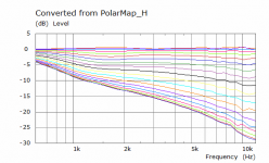
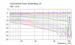
Here are two examples of the difference between the same waveguide in an Infinite Baffle vs a Finite Baffle. If you want to know more accurately what you will get then a 3D sim is necessary with a baffled waveguide.
Attachments

Does this also mean that a compensative widening in the transition area above 2 kHz is advised?
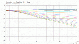
No, that area won't change much. Here's some data I posted last year:
Grey is simulated with an infinite baffle. The colorful lines are measured data in an enclosure (see this post for more info on my speaker build). Ignore the small glitches in the simulated curves.
I also compared my measured curves (same as above) to a simulated cylindrical enclosure in this post.

Thanks guys, I should be good then and will give it a try asap. Maybe Celestion is so kind to tell me which throat length the CDX1-1747 has, mailed them this morning. I would optimize for this as mabat suggested. You did use the same driver bmc0. You also know the throat length?
No, there was no conclusion, as far as I can tell. The CE series is as much flat as possible. The ST260 has already somewhat rising DI, so it can have a more or less flat on-axis FR. And there's the ST280E, downright beaming device but with a higher horn loading down to lower frequency - as low as practicable for a 1" driver. It's up to everyone to try and decide.On another note: I tried to read through all of the DI discussion beginning at #4186 but might have missed it. Was there ever a conclusion or a common decision for one of the options discussed? I think there wasn't. On which ground was the DI slope of the current ST and CE devices picked?
Last edited:
With the device whose ath report I presented in #7908, I might have tricked myself. I would be glad if someone could enlighten me and clear my doubts on this question. I chose a coverage angle of 50 degrees (equalling 100 degrees total if I read the manual correctly), the reasons twofolded. The idea was to increase the dispersion to get a more spacial sound. The DI is a little higher and polars a bit wider than with a 45 degree coverage angle. But here come the doubts: Am I not increasing direct sound thereby? Because the coverage angle, compared to a direct radiator, is still rather small, making the coverage angle wider would only affect a the listening window angles considerable, while not altering the general footprint of early reflections too much. The coverage of a waveguide might simply be too restricted for this. If that is correct, wouldn't a wider coverage angle further reduce spacial cues from early reflections and envelopement, because the listening window is extended?
Speaker placement and orientation, together with a room acoustic treatment will have much bigger effect on percieved sound than whether is the beamwidth 90 or 100 deg.
Do it as smart people do: http://www.gedlee.com/Papers/Philosophy.pdf 🙂
Do it as smart people do: http://www.gedlee.com/Papers/Philosophy.pdf 🙂
With the device whose ath report I presented in #7908, I might have tricked myself. I would be glad if someone could enlighten me and clear my doubts on this question. I chose a coverage angle of 50 degrees (equalling 100 degrees total if I read the manual correctly), the reasons twofolded. The idea was to increase the dispersion to get a more spacial sound. The DI is a little higher and polars a bit wider than with a 45 degree coverage angle. But here come the doubts: Am I not increasing direct sound thereby? Because the coverage angle, compared to a direct radiator, is still rather small, making the coverage angle wider would only affect a the listening window angles considerable, while not altering the general footprint of early reflections too much. The coverage of a waveguide might simply be too restricted for this. If that is correct, wouldn't a wider coverage angle further reduce spacial cues from early reflections and envelopement, because the listening window is extended?
All of the subjective listening tests seem to indicate that people prefer speakers with a wider beamwidth.
One thing that you can use to your advantage, is to shape the enclosure in such a way that it extends the beamwidth control down to 500Hz or even 250Hz. Check out the Klippel measurements on erinsaudiocorner and audiosciencereview, and you'll see that there are speakers with relatively small waveguides that offer beamwidth control down to 500Hz. This is achieved by a combination of enclosure geometry and waveguide geometry.
I realized it doesn't really make sense to me to keep it secret, so here it is - the CE360.
I have only one request - please give credit where credit is due.
I have only one request - please give credit where credit is due.
Code:
[b]; CE360
; 2021 Marcel Batik, licensed under CC BY-NC-SA 4.0
; Ath version 4.7.1[/b]

Throat.Angle = 12.24
Throat.Diameter = 25.4
Throat.Profile = 1
Coverage.Angle = 41.91

Length = 107.7

Rollback = 1
Rollback.Angle = 180
Rollback.Exp = 1.5
Rollback.StartAt = 0.585

OS.k = 1.30

Rot = 3.26

Term.n = 4.03
Term.q = 0.996
Term.s = 1.32

Source.Shape = 2

Mesh.AngularSegments = 8
Mesh.LengthSegments = 60
Mesh.RearShape = 1
Mesh.SubdomainSlices =
Mesh.WallThickness = 6

ABEC.MeshFrequency = 33000
ABEC.NumFrequencies = 100
ABEC.SimProfile = 0
ABEC.SimType = 2
ABEC.f1 = 500
ABEC.f2 = 20000

ABEC.Polars:SPL = {
  MapAngleRange = 0,180,37
  Distance = 2       ; [m]
}

Output.ABECProject = 1
Output.STL = 0

Report = {
  Title = "ATH Cutting Edge Series CE360"
  Width = 1200
  Height = 800
  NormAngle = 10
}- Home
- Loudspeakers
- Multi-Way
- Acoustic Horn Design – The Easy Way (Ath4)