It looks like it's behind the baffle. Try to set an "Offset" in the "Polars" definition so that the center of the polar arc is in front of the baffle.
Sorry, no JMLC or Iwata. But you can model plenty of mediocre or even bad horns with the OS-SE formula alone, there's really no need for anything different with different names. 😉What about JLMC Iwata? Can it be modelled too?
Last edited:

Sorry, no JMLC or Iwata. But you can model plenty of mediocre or even bad horns with the OS-SE formula alone, there's really no need for anything different with different names. 😉
You mean JMLC Iwata horns are mediocre? 😉
I hope this sort of user questions, as opposed to developer discussions, is okay here. If not, let me know if there is a better place.
For a baffle-mounted axisymmetric device the size of a 12 inch-woofer (final target 320 mm), I am using various ratios of the parameters s, n, q and OS.k. I have studied their behaviour, but I could not develope an understanding how I can do the following: raise the UHF gain while controlling the HF. While a faster transition from mouth to OS (smaller OS.k) provides loading in the 5-10 kHz area, I am struggeling to solely affect the 8-15 kHz area, while dampening the frequencies below. Any tips?
For a baffle-mounted axisymmetric device the size of a 12 inch-woofer (final target 320 mm), I am using various ratios of the parameters s, n, q and OS.k. I have studied their behaviour, but I could not develope an understanding how I can do the following: raise the UHF gain while controlling the HF. While a faster transition from mouth to OS (smaller OS.k) provides loading in the 5-10 kHz area, I am struggeling to solely affect the 8-15 kHz area, while dampening the frequencies below. Any tips?
What about JLMC Iwata? Can it be modelled too?

Here's an Iwata horn

Here's a JBL biradial, definitely some similarities to Iwata
Here's how you might be able to simulate Iwata in ath:
First of all, take a look at page 35 of the manual. In there, you can see that it's possible to vary the beamwidth of the waveguide based on the angle.
Once that makes sense, you'll realize you can also vary the LENGTH of the waveguide based on angle. For instance, you can have a waveguide that's longer on the Y axis than it is on the X axis. And once you do that, you can begin to approximate an Iwata horn. Keep in mind that an Iwata and a JBL biradial horn are basically based on circles and spheres which are rotated about the axis of the horn.
Having said all of that, my current project uses a horn that's biradial-ish, and I had to design it in plain ol' 123D, because I couldn't come up with a satisfactory solution in ATH. (I tried.) (https://www.diyaudio.com/forums/multi-way/374570-nightmare-labor-day-10.html#post6762519)
One of the tricky things about ATH is that if you start go manipulate the parameters to come up with weird shapes, the waveguide can't be terminated on a flat baffle.
IE, if you managed to make something like this using a formula, there's no way to attach it to a baffle:
While it's definitely possible what Patrick suggests (i.e. to create a horn with varying length, coverage angle, etc.), I have yet to see one that would perform better than a "simple" axisymmetric waveguide in the end. It seems that the trick is not in the complexity but quite on the contrary. A pure spherical sound wave is pretty simple after all. And that's what we want, right?
Last edited:
I was wandering if throughout the threat opinions where revised, i. e. that an eliptical mouth is better than an axisysmmetric. Has the termination of the OS-curve solved the problems completely which previously where held to be the properties of a axisymmetric device? After all, most seem to use 3D printers and squeezing the mouth ibto a moderate eliptical shape would not change the effort.
I can only say that the best results I ever obtained were with circular mouths. It may be partly because axisymmetric is so easy to work with, but at least it's definitely not an obstacle preventing perfect results. You would have to have a very good reason for a non-circular shape to begin with, IMHO. Based on my experience, you will lose some of the pristine quality but you may gain something else (just can't imagine at the moment what it could be).
Last edited:
I am pretty satisfied with my Iwata-220. Sound more open and less like a well/barrol than my Kugelwellen round horn. Now it handles 300-2500Hz, but plan is to use a iwata 600 from 1400Hz, according JMLCs own design. To lowpass the dirty woofer already at 300Hz is a blessing.
Attachments
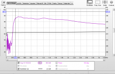
Then it's definitely a progress 🙂Sound more open and less like a well/barrol than my Kugelwellen round horn.
Seriously, if it sounds like a well or barrel, something must be terribly wrong. No horn should sound like that.
My round horn measures really good, but this is just a matter of taste, and the difference is so small that I can live with round horns for the rest of my life, no problem. I can find the measurement for the round horn as well tonight. I have experienced it on all round horns I have listened to and it was only possible to hear after when A-B testing with horns like Iwata. I don't like square horns at all, of the ones I have listened to. I don't think there is a reason to use square shaped horns unless you are limited to plywood boards.
Last edited:
Seems like a bad luck to me. A claim that all circular horns sound like that would be of course not true, as there are counterexamples. But I have no doubt that there are plenty of quite bad circular horns out there. Maybe even majority, especially in some circles. And of course plenty of pretty bad rectangular horns as well.
Last edited:
I would love to see a separate thread on printing an Iwata.
OS waveguides are a different approach than JMLC, etc.
I am interested in experimenting in both.
Doug
OS waveguides are a different approach than JMLC, etc.
I am interested in experimenting in both.
Doug
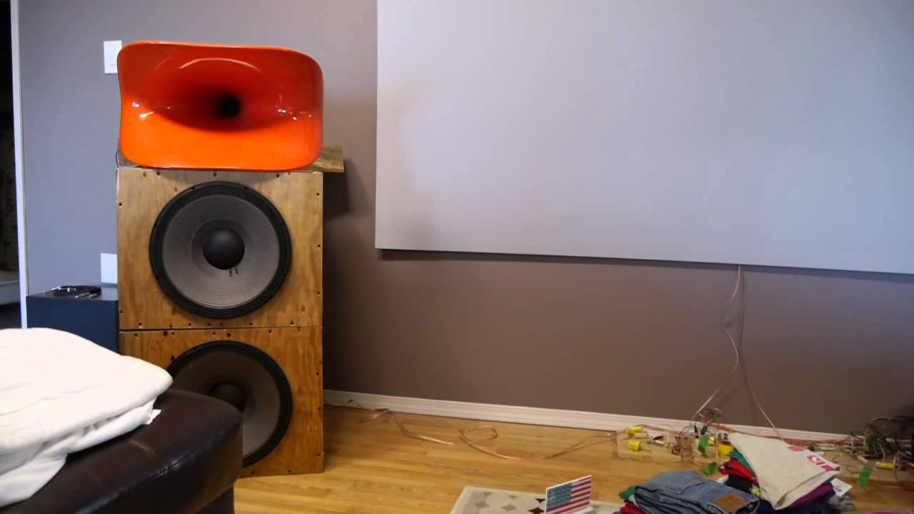
Is there a way to model the response when a freestanding axisymmetrical waveguide is “interrupted” when the axisymmetry is “carved into” to decrease the center-to-center spacing? Though the attached shows a baffle-mounted waveguide, the image should suffice for clarification
Attachments
I don't think it's possible with Ath in the current implementation. You would have to do it manually.
You can see my best attempt at a "manual" simulation starting here 2 way waveguide speaker build ABEC modellingIs there a way to model the response when a freestanding axisymmetrical waveguide is “interrupted” when the axisymmetry is “carved into” to decrease the center-to-center spacing? Though the attached shows a baffle-mounted waveguide, the image should suffice for clarification
The woofer is simulated as a rigid boundary which is not completely correct so the diffraction effects and spikes are exaggerated but you can see that it does nothing good to the waveguide pattern. The CTC distance needs to fall in the right range either under a 1/4 up to 1/2 a wavelength at crossover or then 1 to 1.4 becomes better when you consider power response and DI smoothness.
The idea that closer is better is not always true so it depends on the overall design if that tradefoff is worth making.
With a freestanding guide it would make more sense to hang the waveguide out and in front of the woofer so the waveguide is in the way of the woofer rather than the other way round if a reduction was needed to make the overall design work better.
Last edited:
You don't need to carve into the waveguide; just mount the woofer from the rear of the baffle...Is there a way to model the response when a freestanding axisymmetrical waveguide is “interrupted” when the axisymmetry is “carved into” to decrease the center-to-center spacing? Though the attached shows a baffle-mounted waveguide, the image should suffice for clarification
- Home
- Loudspeakers
- Multi-Way
- Acoustic Horn Design – The Easy Way (Ath4)