Your friendly gift finally motivated me to set up the software and I got myself accustomed with it yesterday night. I stumbled upon the same question as mga2009's when I was looking at the config file of Tritonia. What precisely means to "scale" when I have a config file at hand? I learned from your thread i. e. that changing the throat means changing the whole waveguide, so I assumed that if I want to scale Tritonia down to 1", I have to care that the other dimensions stay the same. How do I do it? Is it as simple as keeping the length of the waveguide in ratio, i. e. if 36 mm Throat diameter equals a 1.4" CD and 26 mm would equal a 1" CD, I would divide the length of the given waveguide through this ratio?With the code published, you have all the power of Ath&ABEC at your disposal.
There's no single corrent answer, it depens on what you want to achieve. The overall size is related to how low you want the radiation pattern to be controlled and you can keep the same size for 1" as for 1.4" throat, or not, etc. These are really independent issues. You may also want to change the depth (and keep the width&height the same, i.e. decrease the coverage angle), etc, etc. The exact shape will change and that will have some side effects, but that's what is the simulation for.
I'm not sure it works with the latest published Ath version but you may also try to define an item "Scale" in the script, that just scales the whole waveguide in a given ratio, e.g. "Scale = 25.4/36".
You are free to experiment.
I'm not sure it works with the latest published Ath version but you may also try to define an item "Scale" in the script, that just scales the whole waveguide in a given ratio, e.g. "Scale = 25.4/36".
You are free to experiment.
Last edited:
I already made a smaller 1" throat version in the past, this is an excerpt from the script (one of many possible solutions).
One could also simulate a dome tweeter pretty easily, it's all documented in the UserGuide.
; Tritonia Waveguide - 1" version
Throat.Diameter = 25.4 ; [mm]
Throat.Angle = 5 ; [deg]
Throat.Profile = 1
Length = 65 ; [mm]
Coverage.Angle = 50 - 7*pow(cos(2*p),5) - 16*pow(sin(p),12)
Term.s = 0.7 + 0.2*pow(cos(p),2)
Term.n = 3.7
Term.q = 0.995
Morph.TargetShape = 1
Morph.FixedPart = 0.0
Morph.Rate = 3
Morph.CornerRadius = 12 ; [mm]
Last edited:
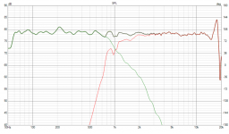
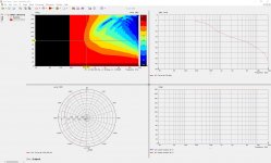
Thanks, I will try. Something I do not understand yet is the VACS output of both your ST260B and Tritonia, compared to ST260. The latter looks as expected and I thought it is something about the range settings, this is ST260:
This is ST260B, and Tritonia looks the same but renders half an hour on my machine, so only ST260B is shown.
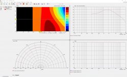
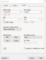
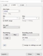
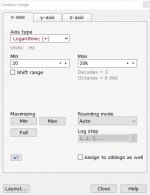
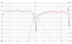
The range settings differ from ST260, where y-axis is 180 and z-axis is -45 to 5 dB. So I thought it be smart to change range settings and here is the result:
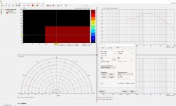
Hm ..

This is ST260B, and Tritonia looks the same but renders half an hour on my machine, so only ST260B is shown.


The range settings differ from ST260, where y-axis is 180 and z-axis is -45 to 5 dB. So I thought it be smart to change range settings and here is the result:

Hm ..
The Tritonia plot is not normalized so you should keep the "absolute" range 10 - 55 dB (or so). You can also convert the polar map to individual SPL curves by "Graph - Convert curves <-> contour", you'll see this clearly in both cases. You can set an angle for normalization as "NormAngle" in the "Polars" item(s) in the Ath script, depending on what you prefer.
Most of the time I normalize plots to 10 deg off-axis (as the ST260 here) but there are many situations where you may want to see an unnormalized plot.
(Normalizing to 10° means that everything is plotted relative to the frequency response at 10°. Which means that the response at 10° itself is shown perfectly flat, the same way as if you equalized the device to be perfectly flat at 10°.)
Last edited:
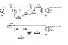
I would be a little concerned and probably would try to tame the driver resonance around 850 Hz. That should not add too much cost to the crossover. Otherwise it looks quite good, IMHO. You don't design the filters with the complete radiation pattern in mind?
Thanks for sharing! It's going to sound marvelous, I have no doubt about that.
Thanks for sharing! It's going to sound marvelous, I have no doubt about that.
Last edited:
I do not want to drift off-topic and allow myself one more remark, though zvu might have read this before. Maybe consider to shelf the HF response of the constant directivity horn. I have done it with my current DSP-speaker but not methodological and am still interested on a more thorough grounding. But here is what Earl Geddes wrote about it: https://www.diyaudio.com/forums/gedlee/264303-na12.html#post4247969 Could be that a flat FR is not desireable, but I have not systematically worked this through.
The ST260 does not have a flat DI, it is rising at about 3db per decade so a flatter on axis sound is more likely to be correct.
......... You don't design the filters with the complete radiation pattern in mind?....
We actually do consider radiation pattern. Lemme explain.
First we measure midwoofer 0 to 90 degrees then the tweeter (i showed tweeter measurements in this thread before). That helps to determine on axis to off axis consistency, direectivity and where the crossover points should be. Averaging those curves shows if there is a sound power problem (sudden dip or a peak that needs attention and is not directivity related). Then, we take separate measurements of tweeter and woofer on axis and roughly 40 degrees off axis. I say roughly because what you really need to do is compare power response (derived from 0-90 horizontal) to measurement at off axis angles. When you hit matching response/tilt, you pick that curve for simulation of off axis response. So two sets of measurements:
1.On axis
Woofer.txt
Tweeter.txt
Woofer+Tweeter in parallel.txt (to be able to derive Z offset of acoustic centers)
2.Off axis ≈ 40 degrees
Woofer.txt
Tweeter.txt
Woofer+Tweeter in parallel.txt (to be able to derive Z offset of acoustic centers)
Old LspCAD enables to switch fast from graph to graph and compare. When you get linear response both on and off axis, it is time to remeasure 180 degrees horizontal and vertical with test filters applied. It rarely needs any serious change in the crossover, just usual tweaking by ear.
But behind all of this a question resides - why the f*** don't we do dual channel measurements and use VituixCAD ? Measure 360 degrees H and V in 10 deg increments would tell us everything and now, right 🙂
Well... Measuring at 3m height to be able to obtain such a high resolution measurements (to be able to actually see what happens in first six-seven octaves without too much software smoothing) does come with some caveats. One of them being a jig with rotation axis right at front baffle plain, that is high enough, stable enough and low diffraction. We have few ideas about how we could do that but (for now) it's just plans. We've made test cabinets that weigh about 40-50 kg each. You need to climb it on a 3 meter height and to be able to rotate it stably. If you look at the pic i posted before, you'll notice that we made speaker stand extension rod with welded plate on top. That plate with extension pipe is screwed on to the test cabinets. That was done on ground and we then lifted the speaker up in the air.
Last edited:
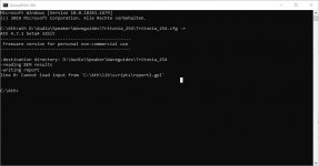
Maybe your are trying to write the report before doing the calculations in ABEC?
Upload your CFG and I will try to run it.
Upload your CFG and I will try to run it.
I am trying to find a practical way of doing the same thing. To help overcome having to lift the speaker so high I have bought an air lift speaker stand. I was concerned it was going to be too wobbly but it is surprisingly solid and as good as any other 35mm stand I have used. This gets it to 2m, there are winch up 3 or 4m lighting stands but they are a lot more money.Well... Measuring at 3m height to be able to obtain such a high resolution measurements (to be able to actually see what happens in first six-seven octaves without too much software smoothing) does come with some caveats. One of them being a jig with rotation axis right at front baffle plain, that is high enough, stable enough and low diffraction. We have few ideas about how we could do that but (for now) it's just plans. We've made test cabinets that weigh about 40-50 kg each. You need to climb it on a 3 meter height and to be able to rotate it stably.
There is a lot of force in the air lift, without a speaker on it takes quite a push to get it back down 🙂
This is the one I bought they seem to be fairly generic
SOUNDKING SB309 SPEAKER STAND WITH LIFT ASSITANCE / GAS LIFT
I'm also printing some adapters to allow a microphone to be mounted on the end of an aluminium tube and have that mounted to a 3m lighting stand as there are no suitable mic stands available off the shelf and studio overhead boom stands are really expensive and still not right.
I am trying to find a practical way of doing the same thing...
That lift tripod sounds great. Gotta check what is available here.
I'm guessing that you will be rotating the microphone to measure horizontal off axis.
How would you do vertical off axis ?
Last edited:
I imagine you should be able to find something as they are quite popular in the live sound market.
These Bespeco ones look good and they do have a 3m version if you can find them
https://www.bespeco.it/en/459-air-cushioned-speakers-stands
I plan to rotate the speaker not the mic. I have a high roofed shed that I hope will let me get between 2 and 3m of distance from the nearest surface.
I haven't decided but I am leaning towards using a large lazy susan type plate at the bottom with 5 degree stops cut in to be held by ball catches so that I only have to move it till it clicks to the next position.
Rotating at the bottom seems safer and easier then I only have to position the baffle of the speaker at the centre of rotation rather than having the stand itself be the centre of rotation.
For vertical I will have to build a triangle support so the speaker can be turned around the other way most probably with a support that goes to the floor with a castor on it to stop side flex.
Yup.We actually do consider radiation pattern. Lemme explain.
First we measure midwoofer 0 to 90 degrees then the tweeter (i showed tweeter measurements in this thread before). That helps to determine on axis to off axis consistency, direectivity and where the crossover points should be. Averaging those curves shows if there is a sound power problem (sudden dip or a peak that needs attention and is not directivity related). Then, we take separate measurements of tweeter and woofer on axis and roughly 40 degrees off axis. I say roughly because what you really need to do is compare power response (derived from 0-90 horizontal) to measurement at off axis angles. When you hit matching response/tilt, you pick that curve for simulation of off axis response. So two sets of measurements:
1.On axis
Woofer.txt
Tweeter.txt
Woofer+Tweeter in parallel.txt (to be able to derive Z offset of acoustic centers)
2.Off axis ≈ 40 degrees
Woofer.txt
Tweeter.txt
Woofer+Tweeter in parallel.txt (to be able to derive Z offset of acoustic centers)
Old LspCAD enables to switch fast from graph to graph and compare. When you get linear response both on and off axis, it is time to remeasure 180 degrees horizontal and vertical with test filters applied. It rarely needs any serious change in the crossover, just usual tweaking by ear.
But behind all of this a question resides - why the f*** don't we do dual channel measurements and use VituixCAD ? Measure 360 degrees H and V in 10 deg increments would tell us everything and now, right 🙂
Well... Measuring at 3m height to be able to obtain such a high resolution measurements (to be able to actually see what happens in first six-seven octaves without too much software smoothing) does come with some caveats. One of them being a jig with rotation axis right at front baffle plain, that is high enough, stable enough and low diffraction. We have few ideas about how we could do that but (for now) it's just plans. We've made test cabinets that weigh about 40-50 kg each. You need to climb it on a 3 meter height and to be able to rotate it stably. If you look at the pic i posted before, you'll notice that we made speaker stand extension rod with welded plate on top. That plate with extension pipe is screwed on to the test cabinets. That was done on ground and we then lifted the speaker up in the air.
- Home
- Loudspeakers
- Multi-Way
- Acoustic Horn Design – The Easy Way (Ath4)
