Marcel, I have a question for you about ATH4 software to be used in a way that it was not originally intended. I need to create a throat adapter shape for a multicell horn. It will be defined by a 2" circle at the driver interface, then morphing to a rectangle with exponential expansion with a given flare rate (in my case 250 Hz). Am I correct that ATH4 could do this if I play a bit with the input parameters? Any hints on how to do this would be really appreciated, since my math skills are not great. Even a simple yes/no would be great, since I think I could figure out what I need over time if it is possible.
I'm not sure. I never bothered with expansion rates, it's even not a properly defined concept, IMO. You could define a simple horn (Term.s = 0) with a higher throat expansion factor (OS.k), like 10, and morph it into a rectangle (I'm not sure how small can be the corner radius, probably not zero). I may try something when I get a chance.
But made this way, the wall tangent angle at the exit of such shape won't be the same everywhere (so it won't match a continuation with a flat wall - this is also in the pipeline, i.e. to implement a "circle to rectangle" adapter feature, that could be extended further with flat panels to whatever length and size).
But made this way, the wall tangent angle at the exit of such shape won't be the same everywhere (so it won't match a continuation with a flat wall - this is also in the pipeline, i.e. to implement a "circle to rectangle" adapter feature, that could be extended further with flat panels to whatever length and size).
Last edited:
Thanks. In Fusion360, I can only do a loft, which has a discontinuity anyway. If I get some reasonably shaped transition, I will be happy. Time for experimenting now. But I think even the loft with some putty and sanding will be as good as fully made by hand. The adapter feature would be great also for Synergy style horns.
Yeah, I think that at the moment you won't get any better results with Ath than with the loft in Fusion.
Thanks. In Fusion360, I can only do a loft, which has a discontinuity anyway. If I get some reasonably shaped transition, I will be happy. Time for experimenting now. But I think even the loft with some putty and sanding will be as good as fully made by hand. The adapter feature would be great also for Synergy style horns.
Look into "curvature continuous" lofts. I'm not familiar with Fusion360 in particular, but this is a very common surface modelling operation and I'd wager someone has figured out a method. You want at least G2 continuity between the loft and the inner surface of the horn.
Well, I am a 3D modeling noob and I am struggling with this quite a bit. I tried to generate something with ATH, it does not really fit this application. I think I will try to ask at the F360 forum how to solve this.
Try to find some tutorials on Youtube, there should be plenty.
Stuff like: 360 LIVE: Lofting to new heights - YouTube
Stuff like: 360 LIVE: Lofting to new heights - YouTube
Marcel, I have a question for you about ATH4 software to be used in a way that it was not originally intended. I need to create a throat adapter shape for a multicell horn. It will be defined by a 2" circle at the driver interface, then morphing to a rectangle with exponential expansion with a given flare rate (in my case 250 Hz). Am I correct that ATH4 could do this if I play a bit with the input parameters? Any hints on how to do this would be really appreciated, since my math skills are not great. Even a simple yes/no would be great, since I think I could figure out what I need over time if it is possible.
For optimum results, don't lose any sleep worrying about "flare rates."
Focus on creating a spline that matches the input with the output.
This is the entire concept of the oblate spheroidal waveguides, you are basically creating a smooth transition from one shape to another.
I prefer 123D to Fusion, and one "neat" thing is that you can basically let the software create a smooth transition between two shapes. This is especially important if the aspect ratio of the two shapes are different. For instance, if you have a horn throat that's circular and measures 1" in diameter, but you have to mate that with something that measures 4" x 1.5" and is rectangular.
Basically, the software can take care of that for you, in various ways. I prefer to smooth the two shapes, but "loft" works too. I generally opt for the former because it lets me control how much smoothing is applied. IE, sometimes you want the transition between the two shapes smoothed for a fraction of an inch, not the entire shape.
You can loft with guide rails to go between two profile on the path you choose. The rails need to touch both profiles so use project include in the sketches to make sure they intersect. Using four or more helps to make sure the loft isn't warped.Thanks. In Fusion360, I can only do a loft, which has a discontinuity anyway.
You can loft with guide rails to go between two profile on the path you choose. The rails need to touch both profiles so use project include in the sketches to make sure they intersect. Using four or more helps to make sure the loft isn't warped.
If you could somehow do screenshots or video of this that would be awesome. I use guide rails but never with project, I'm not sure how that works.
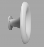
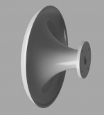
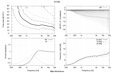
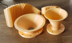
Out of fun I prepared something a little different, for those able to print it cheaply: ST280E (STL+STEP)
Would love to hear some listening impressions one day, especially compared to the ST260.
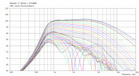
⌀284 x 130 mm, 1" throat / 13.5° total included angle.
Would love to hear some listening impressions one day, especially compared to the ST260.
⌀284 x 130 mm, 1" throat / 13.5° total included angle.
Attachments
Last edited:
Thanks again mabat!
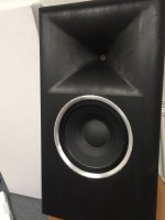
I’ve been listening to my custom waveguide, HF10AK + 12P80ND combo for a few months now.
Off-axis is sublime. I’m overjoyed with the result.
��
I’ve been listening to my custom waveguide, HF10AK + 12P80ND combo for a few months now.
Off-axis is sublime. I’m overjoyed with the result.
��
Attachments
-
 AB6C27F0-F898-4D1D-B2F2-254DF548DD1E.jpeg452.8 KB · Views: 400
 -
 5780C829-C75C-4335-83B2-192E739DAE10.jpeg125.3 KB · Views: 324
 -
 1313596E-807D-4F96-BB5F-E4B73B2FA3E0.jpeg109.1 KB · Views: 358
 -
 CA5B5863-0632-4726-BA15-CDC43842129E.jpeg87 KB · Views: 667
 -
 789F2977-66F8-43AA-81A6-A3587F74B27B.jpeg299.1 KB · Views: 650
Last edited:
Maybe this will help show itIf you could somehow do screenshots or video of this that would be awesome. I use guide rails but never with project, I'm not sure how that works.
Solved: Going nuts trying to get lofting on spline rails - Autodesk Community
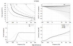
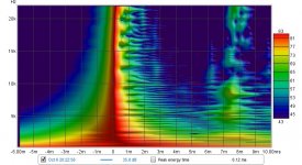
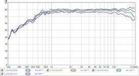
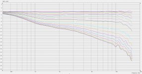
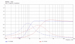
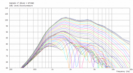
A direct comparison of the ST260 and the ST280E, using a generic 1" driver model.
Here's the driver LE model:
Def_Driving
Value=2.83 IsRms
Def_Driver 'Drv1'
dD=44mm
Mms=0.8g
Cms=30e-6m/N
Rms=3.0Ns/m
Bl=7.5Tm
Re=6.3ohm
fre=35kHz ExpoRe=1
Le=0.1mH ExpoLe=0.618
System 'S1'
Driver 'D1' Def='Drv1' Node=1=0=10=20
// Rear volume
Enclosure 'Eb' Node=20
Vb=50cm3 Qb/fo=0.1
// Front volume
Duct 'D1' Node=10=200
dD=44mm Len=0.5mm
// Phase plug (simplification)
Waveguide 'W1' Node=200=300
STh=1.52cm2 dMo=20mm Len=22mm Conical
// Conical section between phase plug and exit
Waveguide 'W2' Node=300=400
dTh=20mm dMo=25.4mm Len=22mm Conical
RadImp 'Throat' Node=400 DrvGroup=1001
Attachments


Last edited:
US10777172B1 - Folded horn acoustic guitar
- Google Patents
Check this out if you like horns. I am going to put two of them in an acoustic guitar. Each one is five foot long to capture the 1/4 wavelength of lowest acoustic guitar frequency.
- Google Patents
Check this out if you like horns. I am going to put two of them in an acoustic guitar. Each one is five foot long to capture the 1/4 wavelength of lowest acoustic guitar frequency.

- Home
- Loudspeakers
- Multi-Way
- Acoustic Horn Design – The Easy Way (Ath4)