Really nice work here!!
I looked at my input jack threads and they come out as far as these. I had no issue with getting the nut on either. Wonder if there was some play in the mounting holes that allowed the jack to get soldered in more towards the rear of the ODA?? or Maybe the jack itself was a little outside of its physical spec or combination of both??
The labeling really looks nice!!
Alex
Front Panel Express can engrave artwork and can work on aluminum cases
Thanks! I learned some interesting things that Front Panel Express can do along the way in building this one. They can convert a graphic into an HPGL format engraving file - for a whopping $180 per graphic - and then engrave the art! The actual engraving cost after the file conversion is not much, $5 - $15 or so depending on the extent of it and color fills.
Turns out FPE can engrave the top of (aluminum, they can't do steel) Box Enclosures cases too along with just front panels, but same deal they need a viable HPGL file either supplied or pay to have them convert.
I also learned that the 0.2mm engraving tool in their Front Panel Designer program cuts 0.2mm deep, the 0.4 tool 0.4mm deep, and the various "cutter" tools (different widths) in the list cut 0.6mm deep. So you can play around with getting some 3D effects with the various cut depths on text. 🙂
Yeah on those 3.5mm jack threads, when I'm screwing the front and back panels on an ODA I usually use an impact driver (Makita TD090D with a T10 torx bit) to drive the screws about 90% of the way in, then a hand T10 wrench to snug them down. Well this time I noticed that even at the 90% level for the case screws that 3.5mm jack threaded nose still wasn't sticking out. It wasn't until I finished off that last 10% of case screw travel that the nose finally came out. I had a bit of an "aha" moment then about why folks were having some questions.
Switchcraft unfortunately has put one of the solder legs right near the front of the vertical 3.5mm jack, which limits how close it can be to the edge of the board. If I ever do another ODA version in the future I could probably move the jack forward enough to expose one more thread, but that's about it.
Really nice work here!!
Thanks! I learned some interesting things that Front Panel Express can do along the way in building this one. They can convert a graphic into an HPGL format engraving file - for a whopping $180 per graphic - and then engrave the art! The actual engraving cost after the file conversion is not much, $5 - $15 or so depending on the extent of it and color fills.
Turns out FPE can engrave the top of (aluminum, they can't do steel) Box Enclosures cases too along with just front panels, but same deal they need a viable HPGL file either supplied or pay to have them convert.
I also learned that the 0.2mm engraving tool in their Front Panel Designer program cuts 0.2mm deep, the 0.4 tool 0.4mm deep, and the various "cutter" tools (different widths) in the list cut 0.6mm deep. So you can play around with getting some 3D effects with the various cut depths on text. 🙂
Yeah on those 3.5mm jack threads, when I'm screwing the front and back panels on an ODA I usually use an impact driver (Makita TD090D with a T10 torx bit) to drive the screws about 90% of the way in, then a hand T10 wrench to snug them down. Well this time I noticed that even at the 90% level for the case screws that 3.5mm jack threaded nose still wasn't sticking out. It wasn't until I finished off that last 10% of case screw travel that the nose finally came out. I had a bit of an "aha" moment then about why folks were having some questions.
Switchcraft unfortunately has put one of the solder legs right near the front of the vertical 3.5mm jack, which limits how close it can be to the edge of the board. If I ever do another ODA version in the future I could probably move the jack forward enough to expose one more thread, but that's about it.
Last edited:
Here is my build. What an absolute joy to listen to!! Thank you, agdr!

This design is fantastic! Following the build guide was fun and exciting. Truly one of the most rewarding projects I've ever worked on.
This design is fantastic! Following the build guide was fun and exciting. Truly one of the most rewarding projects I've ever worked on.
I also just wanted to say I'm very appreciative for your quick responses whenever I had any problems.
I made a few mistakes along the way (soldered the wrong voltage regulators in the wrong place, soldered a twisted pair wire in the wrong hole) and your debugging tips made identifying and fixing them a breeze! Not to mention you provided me with replacement parts I may have damaged!
What you're doing for this community is unmeasurable! Kudos to everything you've done for us and keep it up!
Ditto here!
Agdr has helped me and many others in both the ODA and O2....from his O2 booster board, to the ODA and anything else electronic!
Ever since nwavguy disappeared agdr has taken up the mantle and helped make the O2 better and birthed the ODA. There DIY community is appreciative of his help.
Its really neat to build a ODA and have it work and work very well..... its a special amp and is my favorite.
I am sure agdr will have other updates and designs in the future.... he sure likes to mess around with electronic circuits and we all benefit!!
Thanks Agdr!
Alex
allindaze - congratulations on your build! 🙂 Looks great. Finishing one of these represents a lot of SMD and through-hole DIY soldering work.
Alex - thanks! 😀
Alex - thanks! 😀
Yes indeed it is one of the best sounding headphone amp around. Well worth the work to solder all these smd parts. I have about 10 cans amps, and the ODA amp is among the top 2-3. Well recommended 😛
Algar_emi - hey thanks for the feedback! 🙂 Good to hear that the ODA is holding its own in the collection. 😀
50Hz Euro/UK transformer build for the ODA
I think it has been mentioned in the thread a few times that we've hit a glitch with the european energy efficiency rules. AC wall transformers are no longer allowed. Everything has to be the (more efficient) DC switchers. Which is great unless you want a linear supply rather than a switcher for your audio gear - and your amp needs AC input!
Up until now everyone outside the US who have built an ODA have boxed up their own torrroidal transformers. I've been hestant to build or even specify something with a line cord that I couldn't test. But it finally occurred to me that 50Hz transformers run just fine on 60Hz, the other way around is the (heating) problem. So I've helped louiebh build up an ODA trasformer for UK/EU use. I wanted to share the details as it may help others.
The first problem is that the US part suppliers - Mouser, Digikey, Allied, Newark, etc - only list 60Hz transformers. The overseas suppliers like Farnell only list 50Hz. So right off the bat louiebh had to purchase the transformer in his country and ship it to me in the US. This was a +/-15Vdc rail ODA build, so the transformer was one with two 12Vac 2.2A secondaries that can be wired in series for 24Vac. For a "standard" ODA build with +/-12.5Vdc rails a transformer with two 9Vac 2A secondaries (total of 18Vac in series) would be the one to use.
Then what to mount it in. I went with a Box Enclosures B3-160 case. The transformer data sheet specifies a minimum of 5mm clearance around the sides. This box gives it about 8mm. The long form factor of the box leaves plenty of room on the back for an IEC connector. Using an IEC connector it becomes an easy thing to switch cords to go from a UK plug to an EU plug - or in my case an US power plug to use for 60Hz testing.
I used an IEC jack by Shurter that includes a switch and fuses. I used a 2 pole jack because of my initial testing here in the states, where 230Vac is phase-phase and not phase-neutral. If you are assembling this in the UK/EU you could use just a single pole unit. The fuse drawer and the fuses in this jack all have to be orderd separately. The jack is Mouser #693-DD11.0121.1110, or Allied #70080287 (Allied sells the B3-160 cases, so you can get both at the same time). The fuseholder is Mouser #693-4301.1401 or Allied #70080677. The fuses are the 5x20mm size, Mouser #693-2010.0021 (2.5A slow blow) or Allied #70160339 (2A slow blow). Tip on the fuses - get the Shurter fuses, they are only 60 cents or so each. For some reason the major brand like Buss in 5x20 slow blow was like $6 each!
The particular power cord involved also has an embedded fuse, but hey you can never be too safe! 🙂 The US cords are also not fused. I have to say I'm just in love with UK/EU power parts!! Geezzz, our 120Vac here just isn't enough for large space heaters and such without going to enormous plugs made for clothes driers at 230Vac. The 120Vac plugs here are relatively tiny and are easily knocked loose from the socket. Gravity always wins over time if a larger wall power transformer is involved. The UK/EU plugs are fantastic IMHO from a physical standpoint. I wish we had EU/UK power in the US!!
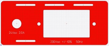
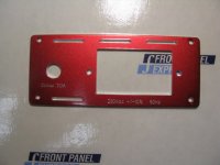
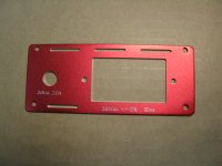
The rear panel on this was drilled out and engraved by Front Panel Express. I've included their .fpd cad file below. In this case the blank pre-colored panel from the case was sent to FPE to use, so the CAD drawing does not include the four mounting holes at the corners. I put the slots on the top and bottom for ventilation.
Photos are below:
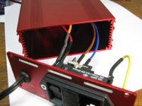
* 3375 shows the IEC jack wired to the transformer and 2.1mm/5/5mm power barrel cable cord. That is double wall heat shrink over the wire-to-wire solder connections and the Faston connectors. The Shurter jacks use the harder-to-find 0.186 wide (and thick, there is also a thin) Faston - something else worth getting from Mouser since you probably won't be able to find it on the shelf anywhere. The loopbacks putting the two primary windings in series for 230Vac and the two secondardy winding in series for 24Vac are just done with solder and heat shrink.
* #3376 shows the clearance around the transformer. It comes with the typical rubber pads for top and bottom, mounting bolt, metal cap and nut. The challenging part was getting the nut and a lockwasher to stay put while threading the bolt, since you really can't get a finger or pliers in that small space on top. 😱 I eventually discovered that a piece of duct tape (what else? 🙂) over the nut and washer works miracles for holding them to the plate while threading the bolt.
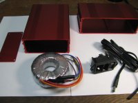
* #3377 shows that there is plenty of space left in the B3-080 case for the IEC and output cable wiring. BTW, if you are using the 2x 9Vac 2A transformer for the standard O2 +/-12.5 Vdc rail build, it might fit in the less-tall B2-160 case. I just had a quick look at it along the way, you would have to take a closer look at the dimensions to be sure. Those mounting bolts on the IEC connector are flat heat metric M3 stainless steel hardware from boltdepot.com.
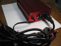
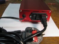
* 3378 & 3379 show the back panel attached to the case and cord plugged in. Push hard! At first I thought the cord was bad it was so loose in the IEC socket. But then I realized I just hadn't pushed it in hard enough. Nice tight solid fit. The grommet for the 24Vac cord is a Keystone 735, Mouser #534-735.
* 3380 & 3381 show the front and bottom. Those rubber feet are the same adhesive backed one in the ODA hardware kit.
* The next photo is a screen grab of the panel from the .fpd CAD file. Remember you can download the Front Panel Designer program for free (to read this file) at the Front Panel Express website.
* The next two are the panel back from FPE, and the final is just the parts laid out.
I think it has been mentioned in the thread a few times that we've hit a glitch with the european energy efficiency rules. AC wall transformers are no longer allowed. Everything has to be the (more efficient) DC switchers. Which is great unless you want a linear supply rather than a switcher for your audio gear - and your amp needs AC input!
Up until now everyone outside the US who have built an ODA have boxed up their own torrroidal transformers. I've been hestant to build or even specify something with a line cord that I couldn't test. But it finally occurred to me that 50Hz transformers run just fine on 60Hz, the other way around is the (heating) problem. So I've helped louiebh build up an ODA trasformer for UK/EU use. I wanted to share the details as it may help others.
The first problem is that the US part suppliers - Mouser, Digikey, Allied, Newark, etc - only list 60Hz transformers. The overseas suppliers like Farnell only list 50Hz. So right off the bat louiebh had to purchase the transformer in his country and ship it to me in the US. This was a +/-15Vdc rail ODA build, so the transformer was one with two 12Vac 2.2A secondaries that can be wired in series for 24Vac. For a "standard" ODA build with +/-12.5Vdc rails a transformer with two 9Vac 2A secondaries (total of 18Vac in series) would be the one to use.
Then what to mount it in. I went with a Box Enclosures B3-160 case. The transformer data sheet specifies a minimum of 5mm clearance around the sides. This box gives it about 8mm. The long form factor of the box leaves plenty of room on the back for an IEC connector. Using an IEC connector it becomes an easy thing to switch cords to go from a UK plug to an EU plug - or in my case an US power plug to use for 60Hz testing.
I used an IEC jack by Shurter that includes a switch and fuses. I used a 2 pole jack because of my initial testing here in the states, where 230Vac is phase-phase and not phase-neutral. If you are assembling this in the UK/EU you could use just a single pole unit. The fuse drawer and the fuses in this jack all have to be orderd separately. The jack is Mouser #693-DD11.0121.1110, or Allied #70080287 (Allied sells the B3-160 cases, so you can get both at the same time). The fuseholder is Mouser #693-4301.1401 or Allied #70080677. The fuses are the 5x20mm size, Mouser #693-2010.0021 (2.5A slow blow) or Allied #70160339 (2A slow blow). Tip on the fuses - get the Shurter fuses, they are only 60 cents or so each. For some reason the major brand like Buss in 5x20 slow blow was like $6 each!
The particular power cord involved also has an embedded fuse, but hey you can never be too safe! 🙂 The US cords are also not fused. I have to say I'm just in love with UK/EU power parts!! Geezzz, our 120Vac here just isn't enough for large space heaters and such without going to enormous plugs made for clothes driers at 230Vac. The 120Vac plugs here are relatively tiny and are easily knocked loose from the socket. Gravity always wins over time if a larger wall power transformer is involved. The UK/EU plugs are fantastic IMHO from a physical standpoint. I wish we had EU/UK power in the US!!
The rear panel on this was drilled out and engraved by Front Panel Express. I've included their .fpd cad file below. In this case the blank pre-colored panel from the case was sent to FPE to use, so the CAD drawing does not include the four mounting holes at the corners. I put the slots on the top and bottom for ventilation.
Photos are below:
* 3375 shows the IEC jack wired to the transformer and 2.1mm/5/5mm power barrel cable cord. That is double wall heat shrink over the wire-to-wire solder connections and the Faston connectors. The Shurter jacks use the harder-to-find 0.186 wide (and thick, there is also a thin) Faston - something else worth getting from Mouser since you probably won't be able to find it on the shelf anywhere. The loopbacks putting the two primary windings in series for 230Vac and the two secondardy winding in series for 24Vac are just done with solder and heat shrink.
* #3376 shows the clearance around the transformer. It comes with the typical rubber pads for top and bottom, mounting bolt, metal cap and nut. The challenging part was getting the nut and a lockwasher to stay put while threading the bolt, since you really can't get a finger or pliers in that small space on top. 😱 I eventually discovered that a piece of duct tape (what else? 🙂) over the nut and washer works miracles for holding them to the plate while threading the bolt.
* #3377 shows that there is plenty of space left in the B3-080 case for the IEC and output cable wiring. BTW, if you are using the 2x 9Vac 2A transformer for the standard O2 +/-12.5 Vdc rail build, it might fit in the less-tall B2-160 case. I just had a quick look at it along the way, you would have to take a closer look at the dimensions to be sure. Those mounting bolts on the IEC connector are flat heat metric M3 stainless steel hardware from boltdepot.com.
* 3378 & 3379 show the back panel attached to the case and cord plugged in. Push hard! At first I thought the cord was bad it was so loose in the IEC socket. But then I realized I just hadn't pushed it in hard enough. Nice tight solid fit. The grommet for the 24Vac cord is a Keystone 735, Mouser #534-735.
* 3380 & 3381 show the front and bottom. Those rubber feet are the same adhesive backed one in the ODA hardware kit.
* The next photo is a screen grab of the panel from the .fpd CAD file. Remember you can download the Front Panel Designer program for free (to read this file) at the Front Panel Express website.
* The next two are the panel back from FPE, and the final is just the parts laid out.
Attachments
-
 IMG_3375.JPG150.7 KB · Views: 457
 -
 torroid case rear panel.JPG252 KB · Views: 141
 -
torroid case rear 1.zip582 bytes · Views: 67
-
 IMG_3379.JPG149.6 KB · Views: 149
 -
 IMG_3378.JPG149.8 KB · Views: 437
 -
 IMG_3377.JPG144.4 KB · Views: 445
 -
 IMG_3376.JPG134.9 KB · Views: 451
 -
 IMG_3369.JPG156.9 KB · Views: 116
 -
 IMG_3370.JPG173.9 KB · Views: 114
 -
 IMG_3323.JPG150.3 KB · Views: 139
Last edited:
Great Looking!!!
I really like the red case!!
I used the same for my ODA!
Alex
Oh that is right you did! I completely forgot about that. 😱 It really did come out looking sharp. Hopefully louiebh will post some pictures. He did a custom engraving on the front panel which came out looking great, then added a graphic to the top of the case.
Looks like I somehow didn't post the picture of the bottom of the transformer box in the post above. Here it is.
Attachments

On it 🙂...
Hi.
So, last I'm on track again and started to test my ODA last evening.
To my surprise I had no voltage at the regulators... 😉.
Back to reading the istructions I found the wires between J8/9/10/11 🙂.
Happy with that I was able to go to sleep. I will continue this evening with testing.
Could someone please buy a B4-080SI case and post it to me as the only one I can find in Sweden selling it is Farnell and they do not want privateers as customers. PM me if anyone could do me the favor 🙂.
Regards
Thanks agdr. I will reply soon hopefully 🙂
Well, I have voltage at J18/19. Everthing is cool except IC11. It's not burning hot but hottest on the board.
Shouldn't the 2 green leds be lit?
Regards.
Well, I have voltage at J18/19. Everthing is cool except IC11. It's not burning hot but hottest on the board.
Shouldn't the 2 green leds be lit?
Regards.
Here's a recent picture of my build... sending the front and back panels to get machined tomorrow. 😀
allindaze - are you sure about the placement of the LDO's? It seems you have LT1963A at IC7 and LT3015 at IC6... Maybe I got it wrong which explains why mine aint working...
agdr - what goes at IC3,4,6,7?
Regards
Thanks agdr. I will reply soon hopefully 🙂
Well, I have voltage at J18/19. Everthing is cool except IC11. It's not burning hot but hottest on the board.
Shouldn't the 2 green leds be lit?
Regards.
IC11 does run warm normally - do you have the heatsink on it? It mounts on a heatsink that has a solder pin which solders to the PC board. Or not- Turbon, please let me know which version of ODA board you have. I just remembered you may have the 2.0. That may be one thing that changed between 2.0 and 2.1, I moved IC11 back a bit for a longer heatsink. But I have a shorter heatsink too that will fit on V2.0 if you don't have it already. Please let me know.. I also may have changed a resistor value on IC11 between V2.0 and 2.1 to reduce the bias current. Originally I had it set at 15mA from the data sheet, but later realized there is a graph and that was for 125V across the chip. In the ODA's case it works fine with 7mA bias current, which reduces the dissipation.
So let me know which board version you have and if you have a heatsink for IC11.
Remember that you have to jumper your power disconnets JP18 and JP19 across to get the power from the power supply to the rest of the PC board. The green leds won't be lit until then. BUT... make sure the power supply is working first with those voltage measurements in the build instructions. Also if you have V2.0 one of those disconnects may solder side to side and the other up and down. Again, please let me know your board version.
I'll reply to your other post here next with the vregs.
Last edited:
agdr - what goes at IC3,4,6,7?
Regards
Allindaze did have his LDOs switched at one point - you may be looking at a photo he took before he realized they were switched. Easy to do!
IC3, closest to the power switch is the LM317 positive regulator.
IC6 next to IC3 is the LT1963A positive LDO regulator.
IC4 next down the line is the negative LM337 regulator
IC7 next to the RCA jack is the LT3015 negative LDO regulator
The best thing to do on power supply troubleshooting is measure voltage down the chain (with respect to ground at any fo thhe 4 ground pad pins). So on the positive power rail, first measure what you have to JP8 (or JP10) to ground, which is the positive votlage feed from the main recitifers and capacitors. Then measure what you have on JP16 (next to JP10) which is a test point between the pre-regulators and the LDO regulators. That is the output of your LM317 pre-regulator. Then finally measure what you have on JP18, which is the output of the LT1963A positive LDO, but again please let me know which version of ODA board you have. The orientation of JP18 may have changed.
Then same for the negative rail. measure voltages to ground on JP9/JP11, pre-regulator output at JP17, and final output votlage at JP19 (which may rotate again depending on your board version). Also note that on the V2.0 boards, if you have one, it was unfortunately easy to get D4 rotated so that one leg was going into JP11 rather than the diode hole. JP11 is right in front of IC4. That should be the wire coming from JP9 by the big caps, not one leg of D4 diode.
And if you haven't jumped JP18 and JP19 across yet, don't do it until your power supply voltage all measure correctly. And again the direction of jumpering JP19 may have changed if you have a V2.0 board.
Last edited:
Well, I have voltage at J18/19.
Whoops - I missed that you had the correct voltage at J18 and J19. 🙂 Well in that case just jumper then across and that will supply power to the rest of the board. Your green LEDs should light then.
Thanks for clarifying the ICs agdr. My board is a v2.0. I must have missed where to jumper across when it comes to JP18/19. Do you have a picture of the jumpers in place?
Regards
Regards
Thanks for clarifying the ICs agdr. My board is a v2.0. I must have missed where to jumper across when it comes to JP18/19. Do you have a picture of the jumpers in place?
Regards
Mystery solved by reading section 2 of the build instructions 🙂
Will jumper it in the weekend.
Regards
- Home
- Amplifiers
- Headphone Systems
- A version of an O2 Desktop Amp (ODA)