"The foundation of a "CFA" is the lower impedance on the feedback node. So I use a classic VFA circuit but pull the impedance of that node down with a low resistance in the feedback divider."
naaah. The foundation of CFA is
1. The TIS input current is directly related to the value of Rfeedback in CFA - ergo high SR as a matter of course
2. The lower loop gains mean that the OPS pole falls above the ULGF without pole splitting - i.e. no need for dominant pole comp as in classic VFA - ergo wide closed loop bandwidths
Taken together, they usually result in gain/bandwidth dependence being broken, which of course is not the case in MC comp'd VFA's
(CFA can also be dominant pole comp'd . . . but then you of course loose the wide loop gain bandwidth property which some designers see as a virtue)
But, I will step out of this now - I dont want to hijack Tony's thread.
🙂
Last edited:
As for the lack of input decoupling causing oscillation, here is a real life example that you can investigate if you're curious:
http://www.diyaudio.com/forums/solid-state/173462-studio-reference-amplifier.html#post4076796
You can simulate the circuit and add or remove the cap.
http://www.diyaudio.com/forums/solid-state/173462-studio-reference-amplifier.html#post4076796
You can simulate the circuit and add or remove the cap.
...But, I will step out of this now - I dont want to hijack Tony's thread.
OK, lets continue this over in my GFT thread, while I wait for some response on HEC.
Best wishes
David
Fighting the hum ... power supply reloaded ...
Fighting the hum ... power supply reloaded ...
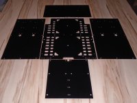
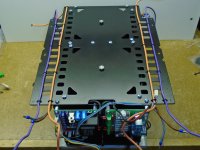
Milling Mu-Metal was a big catastrophe so I decided to go for lasercutted and powder coated steel plates for the powersupply...
... start tuning for lowest SNR with homebrew h-field probe ... need to add some cnc machined mu-metal.
SNR from lab is as low as 125 (A-weighted)
Current SNR is about 110 db (A-weighted)
Picture 3: homebrew h-field probe
Pictures 4 and 5 are showing rectifying spikes. Using the h-field probe it is very easy to find "hum" hotspots. 😉
BR, Toni
Fighting the hum ... power supply reloaded ...
Milling Mu-Metal was a big catastrophe so I decided to go for lasercutted and powder coated steel plates for the powersupply...
Attachments
As for the lack of input decoupling causing oscillation, here is a real life example that you can investigate if you're curious:
http://www.diyaudio.com/forums/solid-state/173462-studio-reference-amplifier.html#post4076796
You can simulate the circuit and add or remove the cap.
I sim that amp (SR200) and it oscillated. I don't know why builder not report the oscillation? I add Miller compensation to stop the oscillation. May be the PCB add some leakage capacitance?
Mu-Metal was a ... catastrophe
I have a mill but I have never tried to work Mu-Metal.
I have read that it is difficult, what was the problem?
I expect soft iron will be quite satisfactory anyway.
Best wishes
David
Hi Bimo i have mentioned it when I construct this amplifier and then found The solution .You can read about this in SR200 tread.I sim that amp (SR200) and it oscillated. I don't know why builder not report the oscillation? I add Miller compensation to stop the oscillation. May be the PCB add some leakage capacitance?
Hi Bimo i have mentioned it when I construct this amplifier and then found The solution .You can read about this in SR200 tread.
Hi, thimios thank you for the information.
Add input filter increase phase margin, but I think amplifier should stable without input filter.
I have a mill but I have never tried to work Mu-Metal.
I have read that it is difficult, what was the problem?
I expect soft iron will be quite satisfactory anyway.
Best wishes
David
The major problem during milling was the cooling of the cutter. I have used automated spray cooling (lubricant: WST20) which seems to be not enough to cool down the cutter. Even manual drilling is difficult - a HSS drill is unusable after some holes.
The soft iron plates weight is of course higher as the aluminium/mu-metal combination. But soft iron is also much cheaper... 😉
BR, Toni
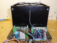
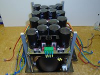
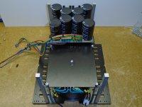
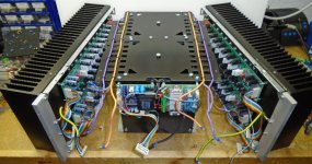
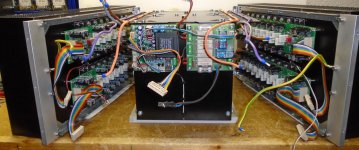
Fighting the hum using soft iron ...
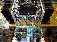
Using soft iron for power supply housing I got it down to
Seems to be my technical limit putting 4 Channels and 2 x 600VA toroids in one case...
THD+N 20Hz - 20kHz 200W@8R below 0.003%
THD+N 20Hz - 20kHz 230W@8R below 1%
THD+N 20Hz - 20kHz 350W@4R below 0.004%
THD+N 20Hz - 20kHz 390W@4R below 1%
(measurement bandwith 80kHz)
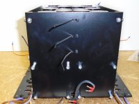
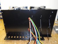
Attached some pictures about "making of" the power supply housing
"part 1".
BR, Toni
Using soft iron for power supply housing I got it down to
- 107 dB SNR full bandwidth and
- 114 dB SNR A-weighted
Seems to be my technical limit putting 4 Channels and 2 x 600VA toroids in one case...
THD+N 20Hz - 20kHz 200W@8R below 0.003%
THD+N 20Hz - 20kHz 230W@8R below 1%
THD+N 20Hz - 20kHz 350W@4R below 0.004%
THD+N 20Hz - 20kHz 390W@4R below 1%
(measurement bandwith 80kHz)
Attached some pictures about "making of" the power supply housing
"part 1".
BR, Toni
Attachments
-
 DSC00145.jpg204.5 KB · Views: 443
 -
 DSC00144.jpg166.6 KB · Views: 426
 -
 DSC00143.jpg180.5 KB · Views: 431
 -
 DSC00136.jpg166.2 KB · Views: 430
 -
 DSC00135.jpg213.8 KB · Views: 450
 -
 DSC00133.jpg210.3 KB · Views: 718
 -
 DSC00129.jpg217.8 KB · Views: 880
 -
 DSC00128.jpg215.1 KB · Views: 907
 -
 DSC00126.jpg201.8 KB · Views: 905
 -
 DSC00124.jpg151 KB · Views: 929
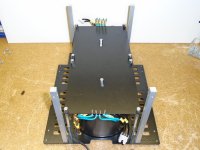
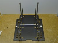
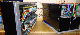
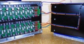
Fighting the hum using soft iron ...
Attached some pictures about "making of" the power supply housing
"part 2".
BR, Ton
Attached some pictures about "making of" the power supply housing
"part 2".
BR, Ton
Attachments
Last edited:
Wow. I am amazed by all the metal machining as much as everything else! 😀
I need to read this entire thread again but where do you think you'd get to with two channels now?
I need to read this entire thread again but where do you think you'd get to with two channels now?
Thx for the kind words!
To achive lowest possible SNR to come close to the lab measurements it may be necessary to build 2 separate monoblocks. Currently an optimized wiring is difficult as 2 channels share one power supply.
One of my next Ideas is to build a 3 channel monoblock tower design placed directly at the speakers with included active crossover.
Br, Toni
I wonder what a modular design in the same chassis would look like i.e. dual mono with room for a third? I'm very intrigued by the performance of the ATI Signature amps versus your project. Of course, I suspect their advertised specs are only good for the two channel amp rather than 7 channels, but it must be quite a feat to have a modular design that can scale the number of channels and still optimise performance.
EDIT: ATI just responded to me re SNR for multiple channels:
EDIT: ATI just responded to me re SNR for multiple channels:
The specifications for THD, signal-to-noise ratio, bandwidth, etc. are identical regardless of the number of channels mounted in the chassis. The only spec that changes is crosstalk.
Last edited:
Thx for the kind words!
To achive lowest possible SNR to come close to the lab measurements it may be necessary to build 2 separate monoblocks. Currently an optimized wiring is difficult as 2 channels share one power supply.
One of my next Ideas is to build a 3 channel monoblock tower design placed directly at the speakers with included active crossover.
Br, Toni
Good plan! Have you read Self’s book on active crossovers? I have it but haven’t had time to study it 🙁
I don’t suppose you could be persuaded to do a write up of this amp design a la Bonsai aka Andrew C. Russell (e.g. http://hifisonix.com/wordpress/wp-content/uploads/2011/03/The_e-Amp_V2.03.pdf?) There’s some really very good stuff in this thread and it would be great to have a summary of the investigations involved and the final conclusions that were reached.
Last edited:
I wonder what a modular design in the same chassis would look like i.e. dual mono with room for a third? I'm very intrigued by the performance of the ATI Signature amps versus your project. Of course, I suspect their advertised specs are only good for the two channel amp rather than 7 channels, but it must be quite a feat to have a modular design that can scale the number of channels and still optimise performance.
EDIT: ATI just responded to me re SNR for multiple channels:
The loss of SNR headroom in my 4 Channel amp may be caused by the facts:
- that 2 channels are sharing one DC power supply.
- that it has no balanced inputs.
- using cheap transformers with e.g. no EMI shield between primary and secondary
- unoptimized cable routing.
I think you should be very proud of your achievement nonetheless.
Have you measured crosstalk? I'm still learning about this stuff but I assume when you measure noise and calculate SNR you are measuring a channel at a time, shorting the input and measuring noise on the output.
Fully balanced typology is likely key. Re toroids, I've found these guys helpful.
Have you measured crosstalk? I'm still learning about this stuff but I assume when you measure noise and calculate SNR you are measuring a channel at a time, shorting the input and measuring noise on the output.
Fully balanced typology is likely key. Re toroids, I've found these guys helpful.
Good plan! Have you read Self’s book on active crossovers? I have it but haven’t had time to study it 🙁
Yes - I have this book (IMHO very good and detailed).
In 2012 I have build a LR24 active crossover and I'm using it for every day listening. The main reason, why I always build 4 channel amplifier...😉
Very good document. If I would have enough spare time...I don’t suppose you could be persuaded to do a write up of this amp design a la Bonsai aka Andrew C. Russell (e.g. http://hifisonix.com/wordpress/wp-content/uploads/2011/03/The_e-Amp_V2.03.pdf?) There’s some really very good stuff in this thread and it would be great to have a summary of the investigations involved and the final conclusions that were reached.
For now there is a maintained index in post #1
BR, Toni
- Home
- Amplifiers
- Solid State
- 2stageEF high performance class AB power amp / 200W8R / 400W4R