Kg,
what do you suggest for post153 solution?
I have the similar in a triple quasi stage to which I added HF and MF decoupling which now allows the output stage to follow the (distorted) signal more accurately.
Dear AndrewT,
would it be possible to show me your solution?
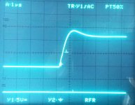
All changes with BC caps and so on does not change the stairs on the rising/falling edge of square root signal. Only stronger compensation smoothes them. Amp is pretty stable and THD20k is very low about 0.003%. No overshoot. No ringing. No spurios oscillation.
Btw: TPC does not have this problem - see attached picture
BR, Toni
Attachments
I don't have a solution, I am looking for a selection of compensations to try on the amplifier.
Ringing only on rising and falling edge?
The amplifier was simply undercompensated in TMC configuration!
On setting TMC values to 100p/220p/2.2k the THD20k+N results are nearly the same as with TPC compensation 100p/100p/3.3k (0.0032% versus 0.0034%). Distortion residual looks identical.
Attached the latest simulation file. PBC's and schematics will be updated the next days so one can decide itself to use TMC or TPC compensation.
PSRR is very good (~ 90 - 110 db). Damping factor about 4000.
Maximum output power with a 2x48VAC / 650VA Toroid is about 220W@8R or 400W@4R.
BR, Toni
Attachments
That still seems like local resonance however, and you have appeased the OPS by increasing compensation, where addressing the source will ultimately make for a more linear and stable amplifier. Of course no one could blame you for seeing the design as finished at this point. However the seeming resolution of this issue may be misleading. Unless you use lead compensation, miller compensation addresses the square corner shape; ringing that starts at the "root" of the square is local ringing of either OPS or the rails usually, and if addressed directly will open potential for a faster and more linear design.
EDIT: Anyways, it's still clear at this point compensation hardly affects THD. So it will probably be more productive at this point to try doubling the Gm of the IPS like I described earlier.
EDIT: Anyways, it's still clear at this point compensation hardly affects THD. So it will probably be more productive at this point to try doubling the Gm of the IPS like I described earlier.
There are a number of factors that affect this type of 'near oscillation'. I like to use ALL that don't cost any more in bits or real estate .. even if they don't show any immediate improvement. A little extra stability in an amplifier as complex and extended as Toni's is always welcome.Kg, what do you suggest for post153 solution?
I have the similar in a triple quasi stage to which I added HF and MF decoupling which now allows the output stage to follow the (distorted) signal more accurately.
But I don't like to do anything which increases THD. IMHO, the mortal sin is anything on the Holy HiZ point at the VAS collector ... so no Ccb on the drivers, Miller & TPC or even evil TMC 😀
One dodge which I sorta think you are suggesting is decoupling the power rails as close to the output devices as possible. The important ones are electrolytics
For Toni, I'd replace his zillion 0u1 on the outputs power rails with the largest electrolytics he could fit in the space. Use good ones cos they will get hot. Electrolytics have just the blend of ESR & capacitance to do what we want.
As we don't sim 'real life' PSU at present, this comes under 'making real life closer to the sim'.
You might find THD20 improves too.
I would do this even if the near oscillation is cured by other means.
__________________
I think Bob Cordell likes to split his Zobels into little bits and have one on each output device. But that costs more bits & real estate. The simpler and tighter you make a circuit, the closer you can get your sim to 'real life'
In Toni's case, a No No! from my point of view is the VAS & IPS on a separate PCB and connected by several inches of ribbon cable. But this is less easy to sort out than simply replacing 0u1 with electrolytics.
__________________
I won't comment on triples cos I've only got 'real life' experience with 'triples + single BJT VAS'. IMHO & E, you get better performance with 'enhanced VAS + EF2' like Toni. My totally prejudiced and without real life foundation view is ... 'triples + enhanced VAS' truly evil 😱
That still seems like local resonance however, and you have appeased the OPS by increasing compensation, where addressing the source will ultimately make for a more linear and stable amplifier. Of course no one could blame you for seeing the design as finished at this point. However the seeming resolution of this issue may be misleading. Unless you use lead compensation, miller compensation addresses the square corner shape; ringing that starts at the "root" of the square is local ringing of either OPS or the rails usually, and if addressed directly will open potential for a faster and more linear design.
EDIT: Anyways, it's still clear at this point compensation hardly affects THD. So it will probably be more productive at this point to try doubling the Gm of the IPS like I described earlier.
Dear keantoken,
maybe lead compensation is the correct way. A quick test with a 1k + 33p below the current mirror and TMC 56p/120p/2.2k shows THD20k+N 0.0035% and the stairs are gone at square root edges.
Don't know if this is the correct, but it helps. About IPS Gm doubling: CCS is currently 4.2 mA. The cascode bjt's are are getting warm to hot at full rail voltage. If I had to double the LTP Iq the cascode bjt's have to be replaced too ...
Give me some time to try your recommendations. Thx for being persistent. 😉
BR, Toni
...
For Toni, I'd replace his zillion 0u1 on the outputs power rails with the largest electrolytics he could fit in the space. Use good ones cos they will get hot. Electrolytics have just the blend of ESR & capacitance to do what we want.
...
In Toni's case, a No No! from my point of view is the VAS & IPS on a separate PCB and connected by several inches of ribbon cable. But this is less easy to sort out than simply replacing 0u1 with electrolytics.
Thx for helping.
The rails at OPS are decoupled by 3 x 470uF ultra low ESR and 8 x 0.1µ as near as possible at every output device. PCB is 70µ and power traces are 15mm wide. Don't think that a wood of "elkos" will better THD or stability. But to test for is not a problem as I can solder them directly to the bjt pins.
I think the ribbon cable is also not the problem as during bread board testing the wires where sometimes longer and sometimes shorter and the stairs at square root edges where already present at lower compensation and before OPS pre-driver change.
Have a look at the very good Nelson Pass's power amplifiers - they have 3 times longer ribbon cables to the power bjt's ...
Don't forget: the BIAS current is very high and every signal cable is separated by a grounded cable. To test if the cable has any influence is simple: using a very short ribbon cable. Will test this the next days.
BR, Toni
Just tested 1.5 inch ribbon cable versus 10 inch ribbon cable with square root. Same stairs on edges in same distance = same frequency. Ribbon cable is really no problem!
BR, Toni
BR, Toni
Hi Toni
I think the values you trying to use for TMC are not correct. I have tested TMC extensively since reading Edmund Stuart´s posts about it and always it has resulted in better performance compared to TPC. The slight ringing is probably due to inadequate gain margin.
The first cap value should be equivalent to the value youd require for just miller compensation so 100pf seems about correct in lieu of your LTP standing current. The second should be at min double this value but better at 3 times the value. Your resistor also seems way too high and should be at least halved.
Theres no problem using 2sa1930/2sc5171 in pairs to increase SOA, I do this all the time, its much better than reverting to onsemi drivers which are as slow as mules. Your base stoppers to these drivers are too low in value though try at least 47 ohm, this is also the key for not requiring a output inductor.
Btw, you should always use a small resistance in series with the bases of your cascodes, these can sometimes oscillate.
I think it is no good idea to measure distortion after output filter zobel / coil during full load. There we would measure added distortion introduced by output coil and load resistors which reacts more like coils.😉 Or am I totally wrong?
Now H2 and H3 compared to their respective residual:
Input from VP7723D: H2 -88/89 dB, H3 -88/89 dB
Output before coil/zobel: H2 -88/89 dB, H3 -88/89 dB
Can't measure a significant difference. 🙂 Maybe the THD analyzer measures now mostly its own noise ..
So for further optimizing I would need better instruments. Maybe there is one out there who can help? Simulation shows we can get THD20k@200W@8R below 0.001%.
Wow - there is really enormous potential in this simple circuit.😎
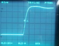
Attached a rising edge of a 10kHz square. ~ 80-90V slew rate.
BR, Toni
Now H2 and H3 compared to their respective residual:
Input from VP7723D: H2 -88/89 dB, H3 -88/89 dB
Output before coil/zobel: H2 -88/89 dB, H3 -88/89 dB
Can't measure a significant difference. 🙂 Maybe the THD analyzer measures now mostly its own noise ..
- TMC values 68p/220p/1k
- LTP compensation (inserted below current mirror ) 100p/330R
- LTP degeneration R8 and R11 (post#1 schematic) from 220R reduced to 100R.
So for further optimizing I would need better instruments. Maybe there is one out there who can help? Simulation shows we can get THD20k@200W@8R below 0.001%.
Wow - there is really enormous potential in this simple circuit.😎
Attached a rising edge of a 10kHz square. ~ 80-90V slew rate.
BR, Toni
Attachments
Hi Toni
I think the values you trying to use for TMC are not correct. I have tested TMC extensively since reading Edmund Stuart´s posts about it and always it has resulted in better performance compared to TPC. The slight ringing is probably due to inadequate gain margin.
The first cap value should be equivalent to the value youd require for just miller compensation so 100pf seems about correct in lieu of your LTP standing current. The second should be at min double this value but better at 3 times the value. Your resistor also seems way too high and should be at least halved.
Theres no problem using 2sa1930/2sc5171 in pairs to increase SOA, I do this all the time, its much better than reverting to onsemi drivers which are as slow as mules. Your base stoppers to these drivers are too low in value though try at least 47 ohm, this is also the key for not requiring a output inductor.
Dear Manso,
thank you for response. The base stoppers of drivers are 10R after 68R - so in sum 78R. To base of other bjt in sum 20R. Do you think there could be a problem? Maybe a oscillation loop between the two drivers? If so, I will change them to 47R - sim shows no problems on doing so.
Cascode base stoppers: afaik Bob and Douglas haven't used them in their books? Is there more information about this or experience?
BR, Toni
..it's going to be a reference amp...
Cheers, Martin
... at least for me! Thx Martin.
Btw.: your BOM for LR24 is on the way. 😉
Br, Toni
Cascode base stoppers: afaik Bob and Douglas haven't used them in their books? Is there more information about this or experience?
"Bonsai" aka Andrew at HiFiSonix has a good article about it.
Check out his website - lots of good stuff there.
"Bonsai" aka Andrew at HiFiSonix has a good article about it.
Check out his website - lots of good stuff there.
Dear Harry,
thx for quick response. Really good prepared info. Thx also to Bonsai for investigation.
BR, Toni
'pure Cherry' with Toni's amp
This is an analysis of the files Toni (astx) posted in #109
http://www.diyaudio.com/forums/solid-state/235188-tpc-vs-tmc-vs-pure-cherry-15.html#post3489738
Toni, my apologies for editing your original but my old eyes need less cluttered stuff to see clearly. Some simplifications:
In general, you keep ‘clean’ GND pristine. But your C3/4 0u1 decouple the small signal stages to ‘clean’ GND. IMHO, this is truly evil and I’ve removed them. This will affect stability & THD in the sims slightly but I’ve not investigated this fully.
I investigate stability with two main methods.
I use .TRANS on the complete amplifier with a variety of capacitive only loads from 33p to 100n. Toni has a 2nd Zobel R84 & C6 on the output which probably helps his amp with wonky loads. I’ve hijacked it to do my stability testing by making R84 0R1 and varying C6
I do the same with the Closed Loop response, .AC to 100Mhz, with the same loads and look for peaking.
I don’t use Bode plots, Phase & Gain Margins to check stability but only for a quick initial look They are useful if you find stability problems and want to improve this. Also useful are the Nyquist curves that LTspice can do but they need to be used in conjunction with Bode plots. They are not alternatives.
.TRANS with reactive loads & different device parameters is a far better indicator of stability. This is of course exactly what you would (should) do in real life too.
This is an analysis of the files Toni (astx) posted in #109
http://www.diyaudio.com/forums/solid-state/235188-tpc-vs-tmc-vs-pure-cherry-15.html#post3489738
Toni, my apologies for editing your original but my old eyes need less cluttered stuff to see clearly. Some simplifications:
- Removing capacitors across ‘perfect’ voltage sources will not affect sim
- Merging series resistors
In general, you keep ‘clean’ GND pristine. But your C3/4 0u1 decouple the small signal stages to ‘clean’ GND. IMHO, this is truly evil and I’ve removed them. This will affect stability & THD in the sims slightly but I’ve not investigated this fully.
I investigate stability with two main methods.
I use .TRANS on the complete amplifier with a variety of capacitive only loads from 33p to 100n. Toni has a 2nd Zobel R84 & C6 on the output which probably helps his amp with wonky loads. I’ve hijacked it to do my stability testing by making R84 0R1 and varying C6
I do the same with the Closed Loop response, .AC to 100Mhz, with the same loads and look for peaking.
I don’t use Bode plots, Phase & Gain Margins to check stability but only for a quick initial look They are useful if you find stability problems and want to improve this. Also useful are the Nyquist curves that LTspice can do but they need to be used in conjunction with Bode plots. They are not alternatives.
.TRANS with reactive loads & different device parameters is a far better indicator of stability. This is of course exactly what you would (should) do in real life too.
TPC version
First for TPC version, we do a Loop Gain analysis with Tian probe in Toni’s original position. LGorg.gif
Then we move the Tian probe to the VAS input, Q6 base, to look at the inner loop. LGvas.gif
Next we decouple the inner loop from the other loops by adding L2 between IPS output, Q25 collector, and the Tian probe for LGvasDecoupled.gif What this shows is that having the main loop operative gives big changes at LF but above 2MHz, phase & gain is practically identical. So if our stability stuff for the inner loop happens above about 1MHz, we can use the Tian probe on the VAS input without considering whether the rest of the loop is closed or not.
TPC.gif shows what we’ve done so far.
Finally we move the Tian probe to the –ve input of the IPS, base of Q9, for LGwhole.gif
All 4 LG plots show what should be a stable amp. Various loads on the Closed Loop plots and .TRANS confirms this. Even more important … ‘real life’ confirms it too.
Distortion at 40Vrms into 8R up to 10th harm, using Eugene Dvoskin’s Total Harmonic Analyzer from the LTspice Yahoo Group, is in THD.gif and THD20.gif The latter shows 2 cycles of fundamental at a level of 0.01% to give some idea of scale … and the Distortion Residual at 20kHz. Ignore the LF stuff. Note the spiky 20kHz residual even with 43mA through each output.
But the THD curves are well in line with what Toni measures.
Attachments


Last edited:
TMC version
Toni says he found the TMC version unstable. If our SPICE model is to be trusted, it should at least suggest problems in this area. Accurate simulation is difficult as this is a big amp with 8 pairs of outputs. Stray capacitances and lead inductances will have much more influence than with a simple 50W amp with only 1 pair of outputs close to the VAS and other stuff. Remember 20nH / inch!
I won’t bore you with a full stability analysis. I couldn’t get the model to oscillate on any ‘linear’ measure or even .TRANS though it came close with certain capacitive loads. The Closed Loop response CL3n3.gif shows what happens with just 3n3 on the output. The sharp Q of the peak is certainly suggests it won’t take much to push this amp into oscillation.
TMC.gif Do we believe this model? Probably. Real life is probably more twitchy cos loadsa extra strays & parasitics.
Attachments
pure Cherry
We convert this into ‘pure Cherry’ by shorting out R27 & removing C7. The Cherry cap is C1 100p. Our first guess at stability tweaking is making VAS emitter R22 = 5.6+22 with C2 1n across it.
1stCherryTHD.gif show the THD performance. LF THD is about the same as the TPC version, HF THD is slightly better but the higher harmonics are much less. 1stCherry20k.gif shows xover spikes have nearly disappeared.
This big change in the residual is a ‘real life’ effect I expect to see.
Stability looks OK on the capacitive loads. But Closed Loop response shows a secondary peak at 20MHz. 1stCherryCL.gif
Sure enough the Loop Gain of the inner loop shows very small Gain Margin at 20MHz. 1stCherryInnerLG.gif
.. but this is just the start of our exploration of ‘pure Cherry’.
Attachments
- Home
- Amplifiers
- Solid State
- 2stageEF high performance class AB power amp / 200W8R / 400W4R