Please don't do this Toni.
Triple EFs are evil. Using them in your excellent design will definitely degrade stability and probably NOT give any better THD. Your design is already better than most designs with triples ... such that it has already attracted favourable comment from triple afficianado, Bob Cordell. 🙂
IMHO, you can get even better performance without increasing the attractive simplicity, with different compensation methods. I see you are already doing this with your variations on TPC.
You might like to try evil TMC and ,, if you are very brave, even 'pure Cherry' http://www.diyaudio.com/forums/solid-state/235188-tpc-vs-tmc-vs-pure-cherry.html#post3474671 😱
Could you send me the latest LTspice .ASC for your amp and also the transistor models? I'd like to see if your excellent circuit can be further improved with 'pure Cherry' .. at least in SPICE world 😀
I've PM'd
I also disagree, I only use triples, many times I dont even need to use a inductor at the output for stability, never had any problems but the benefit of reducing THD by a fair margin.
As an exaple look at Rotel amps, always makes use of Triples and in 80 % of the designs there is no need for output inductors either, they are perrfectly stable though.
Manso, can you tell us how you test for stability? Both in SPICE world and in 'real life'?I also disagree, I only use triples, many times I dont even need to use a inductor at the output for stability, never had any problems but the benefit of reducing THD by a fair margin.
As an exaple look at Rotel amps, always makes use of Triples and in 80 % of the designs there is no need for output inductors either, they are perrfectly stable though.
Also, can you tell us what THD figures you get so we can compare them with Toni's simpler circuit?
Last edited:
It is true that the combination of high loop gain and minimally-invasive compensation can create insidious stability issues, especially if the parasitics of the transistors end up becoming part of the stability compensation. The trick is to swamp out these parasitics without causing more distortion.
Manso, can you tell us how you test for stability? Both in SPICE world and in 'real life'?
Also, can you tell us what THD figures you get so we can compare them with Toni's simpler circuit?
Sorry to jump in here, my amp with output triples is quite stable and in service more then a year with no problem. Audio is just hobby for me(I was telecomunication engineer now retired) and I would be grateful if you simulate that my amp, zipp file with all needed model is here http://www.diyaudio.com/forums/solid-state/182554-thermaltrak-tmc-amp-12.html#post3056483
BR Damir
Sajti, have you a link to your circuits? Are these distortion figures 'real life' or SPICE?
Toni, thanks for the models.
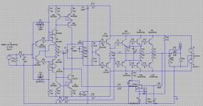
The spice:
Sajti
Attachments
The capacitive loading of the VAS is significant at 680pF. This swamps out any other parasitics at those frequencies. While this is advantageous for stability, VAS loading is actually larger at treble for this design than for many EF2's.
The capacitive loading of the VAS is significant at 680pF. This swamps out any other parasitics at those frequencies. While this is advantageous for stability, VAS loading is actually larger at treble for this design than for many EF2's.
This sets the dominant pole, to 2.2kHz (approx). There is one important issue: The amplifier needs only 330pF compensation if the driver is 5171/1930. Any other driver needs mosre compensation.
So there is one advantage of this method:The output impedance of the VAS is low at the high frequencies. This means lower distortion in the output stage.
Sajti
The output impedance of the VAS is low at the high frequencies. This means lower distortion in the output stage.
Sajti
I've heard this a lot, but it isn't true. The feedback loop at audio largely determines impedance at any given point, so the impedance there is virtual. Any signal passing through that impedance will become part of the distortion in the amp. Low or high impedance it doesn't matter, the active devices still must drive the output stage with the same current. Discrete impedances added after the fact only increase distortion because the feedback loop has to work against them. This is a necessary evil where stability is concerned, and the trick is to add impedances where they do not add to the stages' unique distortion mechanisms.
Sajti, this is an interesting circuit.The spice:
Have you some THD and other performance figures to compare with Toni's results? Preferably 'real life' but SPICE will do .
New driver bjt's (2SC4793/2SA1837 and MJE15032/MJE15033) arrived ...
The good news: 2SC5171 and 2SA1930 can be directly replaced by 2SC4793/2SA1837.
The bad news: the distortion figure of THD20kHz@200W@8R was about 0.0034% before and is now with this drivers 0.005%.
Maybe a compensation tuning helps to get closer to the predicted 0.003% THD from simulation. Let's see.
A complete THD/power test is now running. So we can compare the THD results also for lower level signals.
BR, Toni
The completed THD power test shows significant higher THD levels from low to high power! 🙁
Perhaps the new drivers needs a rebiasing? The new drivers have better SOA so after some simulations i decided to change R17 from 150R to 68R.
Bingo! 10ppm better THD in real life!
THD20kHz@200W@8R is now at 0.004% (measurement floor of VP7723D is at 0.00106%)
THD1K@200W@8R is now at 0.00130% (measurement floor of VP7723D is at 0.00045%)
A 25% difference in THD is pretty small, think in logarithmic terms. I used to worry about small differences but eventually I realized thinking logarithmically allowed me to make gains of more than 6db. Unless your design is nearly finalized, you should not be satisfied with fractional gains or you will spend time on only the minor sources of distortion. Look for the major sources of distortion and focus on eliminating those. To do this requires developing methodology but really it's just a process of asking a question and devising a test that will answer it. Doing this you can figure anything out.
A 25% difference in THD is pretty small, think in logarithmic terms. I used to worry about small differences but eventually I realized thinking logarithmically allowed me to make gains of more than 6db. Unless your design is nearly finalized, you should not be satisfied with fractional gains or you will spend time on only the minor sources of distortion. Look for the major sources of distortion and focus on eliminating those. To do this requires developing methodology but really it's just a process of asking a question and devising a test that will answer it. Doing this you can figure anything out.
you are right regarding THD levels! I see them as a sign that something can be done better. So I found the underbiasing problem of the new drivers very quickly. Also the distortion residual waveform is important and a good sign of stability or instability ...
Btw: It seems to be no more necessary to keep the 22p bridge above TPC in place. Amplifier is stable without it. Will optimize TPC the next days. Square root overshoot is stable - shows no ringing.
All 2SC5171/2SA1930 have now been replaced by 2SC4793/2SA1837 drivers. Slewrate increased from 45V/µs to about 80V/µs. Square root overshoot is TPC typically and stable - shows no ringing.
BR, Toni
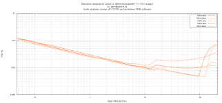
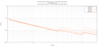
Distortion analysis for R17=68R / 22p removed
All 2SC5171/2SA1930 have been replaced by 2SC4793/2SA1837 including VAS drivers!
2SC4793/2SA1837 are biased with R17=68R
22p bridge capacitor (above TPC) removed.
Note: 20 and 200Hz measurements above 100W are inaccurate as lab powersupply current limiter has actived.
The second plot is the loop measurement of the analyzer itself for comparison.
Attachments
I've seen too many C5171/A1930 counterfeits than I'd like to have. It would not surprise me at all if yours were fakes and were causing stability issues.
At the same time, the C5171/A1930 are actually a bit faster than the C4793/A1830.
Hopefully removing the 22p TPC bridge lowers THD20. Eventually it may become evident that the only distortion left is that from the output stage base currents, in which case it will be time to improve the frontend or change OPS topology. Or let well enough be.
It is possible to correct the overshoot with an RC across the feedback resistor. The idea is to optimize TPC for 6db overshoot and then correct it by lowering gain above the TPC corner by 6db (other figures than 6db could work). This may seem superfluous, but it is important to limit overshoot so that you can test step response close to full output swing where 6db overshoot would clip badly. TPC is often oversized to prevent this overshoot but when it is allowed and corrected for, significant gains can be made (that is, if TPC was the dominant distortion mechanism).
Last edited:
asc file? Thank you.
BR, Toni
I will give it tomorrow, as it is in my home PC.
Sajti
I've seen too many C5171/A1930 counterfeits than I'd like to have. It would not surprise me at all if yours were fakes and were causing stability issues.
At the same time, the C5171/A1930 are actually a bit faster than the C4793/A1830.
Try Mouser. They have stock, and I'm sure that they sell real Toshiba.
5171/1930 is faster, and have lower internal capacitances.
Sajti
I've seen too many C5171/A1930 counterfeits than I'd like to have. It would not surprise me at all if yours were fakes and were causing stability issues.
Don't forget the C5171/A1930 are very fast (for their power rating) - as such they may be more susceptible to parasitic oscillations. astx may have been seeing this rather than global loop instability.
The good news: 2SC5171 and 2SA1930 can be directly replaced by 2SC4793/2SA1837.
The bad news: the distortion figure of THD20kHz@200W@8R was about 0.0034% before and is now with this drivers 0.005%.
Maybe a compensation tuning helps to get closer to the predicted 0.003% THD from simulation.
You say predicted THD with the new drivers is 0.003%, but what models are you using for the C4793/A1837?
- Home
- Amplifiers
- Solid State
- 2stageEF high performance class AB power amp / 200W8R / 400W4R