The used 2SC5171/2SA1930 where original Toshiba from Mouser. Maybe the very high ft (200MHz) leads to more parasitic oscillation?
Good news: On using now 2SC4793/2SA1837 the amplifier is now stable running TMC (yes really: TMC!). With the other bjt's I got the amp not usable stable.
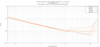
Currently a test is running with TMC values 68p, 120p, 2.2k
(amp comes out of oscillation with 27p and up). First look on THD figures show nearly same results as from post #136
Think we have now more headroom for optimizations. Need a better THD analyzer...
Good news: On using now 2SC4793/2SA1837 the amplifier is now stable running TMC (yes really: TMC!). With the other bjt's I got the amp not usable stable.
Currently a test is running with TMC values 68p, 120p, 2.2k
(amp comes out of oscillation with 27p and up). First look on THD figures show nearly same results as from post #136
Think we have now more headroom for optimizations. Need a better THD analyzer...
Don't forget the C5171/A1930 are very fast (for their power rating) - as such they may be more susceptible to parasitic oscillations. astx may have been seeing this rather than global loop instability.
You say predicted THD with the new drivers is 0.003%, but what models are you using for the C4793/A1837?
Dear Harry,
think the ft 200MHz of C5171/A1930 caused the problems.
The currently used models are 2SC4793_A and 2SA1837_A from keantoken's "standard.txt" a view posts ago... (0.003% was with R17=150)
Attached the current asc file for all who want to experiment with TPC, TMC, ??? ...
Attachments
Harry, that is what I had in mind when I said the OPS needed a capacitive source impedance.
Those models are Andy_C's. I believe he has more models and improved ones as well but I have not been able to find them since his exile.
The models I posted are documented in the .txt file, so they're traceable. JUST SAY NO to mysterious, untested models. Phillips BJT models seem to be an exception; a few of these even have quasi-sat modeling.
So, it doesn't seem stability compensation is a factor yet in THD.
So, you can try reducing distortion this way. Double LTP Gm if possible, then double your compensation. THD should roughly halve. If compensation does not need to be doubled then it is evident your amp has more inherent stability with higher degeneration and you reap extra rewards. You can increase the proportion of compensation to degeneration more if this results in gains, until you begin to see a worsening effect at treble.
If an increase in compensation isn't followed by a proportional increase in LTP Iq, your slew rate will fall, so be aware. This is why so many amps have low THD but not high slew rate. To have both takes some skill.
Hi Toni,
Hope this means you accept ! 😀. Yes with your help the amplifier can be refined much further or may provide us with interesting results.
However we need to establish a baseline, you do have a wonderful lab and wonderful ideas. This provides you with an opportunity to test the listening experience and emotional response of the highly refined amplifier your working on against the 1diffqc amplifier that uses darling-tons.
Thanks for your contributions to audio research.
Pm sent
kind regards,
Harrison.
Can you refine your Ideas?
BR, Toni
So, it doesn't seem stability compensation is a factor yet in THD.
So, you can try reducing distortion this way. Double LTP Gm if possible, then double your compensation. THD should roughly halve. If compensation does not need to be doubled then it is evident your amp has more inherent stability with higher degeneration and you reap extra rewards. You can increase the proportion of compensation to degeneration more if this results in gains, until you begin to see a worsening effect at treble.
If an increase in compensation isn't followed by a proportional increase in LTP Iq, your slew rate will fall, so be aware. This is why so many amps have low THD but not high slew rate. To have both takes some skill.
Dear keantoken,
thank you for providing this optimization guideline. Will try this the next days!
Some words about the current THD plot:
I have measured the THD20k levels of the input signal during max power output test with my HP3585A spectrum analyzer. The H2 level relative to the fundamental is -88,9 dB and the H3 level is about -88.8 dB. H4 and up below 100 dB measurement floor.
So it is clear that the amplifier has to amplify a > 0.001% distorted signal. Is it correct to subtract this known error from the measured 0.0032% or are there other methods for calculating distortion if only spectrum analyzer values are available (relative to fundamental: H2 of output was -86.8 dB and H3 output was 80.9 dB). I think my distortion analyzer has reached his limits some tuning steps before ...
BR, Toni
The used 2SC5171/2SA1930 where original Toshiba from Mouser. Maybe the very high ft (200MHz) leads to more parasitic oscillation
Hi,
I heard, that the 5171/1930 can oscillate, if You use them over 40V PSU. Personally I didn't find it, but it can be true.
The 4793/1837 used by HK990 with +/-80V PSU, without any problem...
Sajti
I somehow doubt that instability is due to voltage variations.Hi,
I heard, that the 5171/1930 can oscillate, if You use them over 40V PSU. Personally I didn't find it, but it can be true.
The 4793/1837 used by HK990 with +/-80V PSU, without any problem...
Sajti
It is much more likely due to current variations.
Look at the datasheet to see the various parameter variations that are plotted against Ic.
I somehow doubt that instability is due to voltage variations.
It is much more likely due to current variations.
It's strange, but there was no relation to the current. Only to the PSU voltage. Small capacitor between the C and B helps. But of course it's slow down the device...
Sajti
Btw: during development I needed 10pF cap between B/C of the drivers to slow down the 2SC5171/2SA1930 and get them out of oscillation ...
This instability has gone with first PCB layout but needed a stronger compensation which was the main reason for the relatively large bridge cap over TPC.
BR, Toni
This instability has gone with first PCB layout but needed a stronger compensation which was the main reason for the relatively large bridge cap over TPC.
BR, Toni
did you change the current inadvertently when you changed the voltages?It's strange, but there was no relation to the current. Only to the PSU voltage. Small capacitor between the C and B helps. But of course it's slow down the device...
Sajti
or
Did you re-bias all the stages such that the same current flowed when at the new voltages?
Ringing only on rising and falling edge?
Amp is stable and working fine with TMC. There is only one thing where I can't find the reason why there is this sort of ringing on rising and falling edge. Frequency is about 5-6 MHz.
Anyone has seen this before? Any Ideas where to start "debugging".
Simulation with square root shows some small signs of the same effect...
Or ignore this as we never amplify "square root"?
BR, Toni
Attachments

This looks like local ringing at the VAS output. Another thing having to do with an OPS that wants a capacitive source impedance. Try hanging a cap off the VAS output again. Maybe this time it needn't be so large. This is similar to using B-C caps on the drivers, just the current loop follows a different path. Either may work. Base stoppers on the drivers is also something you could try. This issue tends to happen with a high-impedance VAS, which tends to occur when one gets close to optimal compensation. It's not a fault of the VAS, but of the OPS, and while appeasement (lowering VAS output impedance) is the most common approach, correcting the source will open up the amp for more potential.
did you change the current inadvertently when you changed the voltages?
or
Did you re-bias all the stages such that the same current flowed when at the new voltages?
As this was the 2nd EF stage, there was only slight changes in the bias (1-2%) as the PSU voltage increased from +/-40V to +/-60V.
But this oscillation was found in another amplifier which is non feedback buffer, made some other diyers. The bias was close 5-7mA range.
Sajti
I'm not sure I understand your question but THD is calculated as the RMS sum of all the harmonics.Is it correct to subtract this known error from the measured 0.0032% or are there other methods for calculating distortion if only spectrum analyzer values are available (relative to fundamental: H2 of output was -86.8 dB and H3 output was 80.9 dB).
ie THD = (H2^2 + H3^2 + .... ) ^ 1/2 where H2 is the level of 2nd harm etc
The code in Eugene Dvoskin’s Total Harmonic Analyzer from the LTspice Yahoo Group makes this clear with a little study.
These have very different effect.Try hanging a cap off the VAS output again. Maybe this time it needn't be so large. This is similar to using B-C caps on the drivers, just the current loop follows a different path.
The Cbc AT the drivers address a 'parasitic' oscillation which is probably not modelled by your sim. C on the VAS output addresses something which shows up in your sim but may have no effect on 'parasitic' oscillation.
Unfortunately, both have the same evil effect on THD 😡
Kg,
what do you suggest for post153 solution?
I have the similar in a triple quasi stage to which I added HF and MF decoupling which now allows the output stage to follow the (distorted) signal more accurately.
what do you suggest for post153 solution?
I have the similar in a triple quasi stage to which I added HF and MF decoupling which now allows the output stage to follow the (distorted) signal more accurately.
I'm not sure I understand your question but THD is calculated as the RMS sum of all the harmonics.
ie THD = (H2^2 + H3^2 + .... ) ^ 1/2 where H2 is the level of 2nd harm etc
The code in Eugene Dvoskin’s Total Harmonic Analyzer from the LTspice Yahoo Group makes this clear with a little study.
Thx Kg!
Are there open resources to "Eugene Dvoskin’s Total Harmonic Analyzer". Don't want to get registered yahoo group member only for reading ...
BR, Toni
Last edited:
This looks like local ringing at the VAS output. Another thing having to do with an OPS that wants a capacitive source impedance. Try hanging a cap off the VAS output again. Maybe this time it needn't be so large. This is similar to using B-C caps on the drivers, just the current loop follows a different path. Either may work. Base stoppers on the drivers is also something you could try. This issue tends to happen with a high-impedance VAS, which tends to occur when one gets close to optimal compensation. It's not a fault of the VAS, but of the OPS, and while appeasement (lowering VAS output impedance) is the most common approach, correcting the source will open up the amp for more potential.
Thx for this debugging formula. Will try this at MEST evening.
BR, Toni
Last edited:
- Home
- Amplifiers
- Solid State
- 2stageEF high performance class AB power amp / 200W8R / 400W4R