Thx! I don't think that the shorter path will better the NFB. Of course if shorter there could be less pollution on the feedback track. But the big iron "SA2014" showed that the feedback wire could be very long.
Signal speed in copper is > 200000km/s ...
BR, Toni
Signal speed in copper is > 200000km/s ...
BR, Toni
Thimios, I mailed 2 x LM317-based aux PSUs and 1 x astx MCU plus a front panel button board to you today. Not sure how long the package will take to reach you but likely 3-5 days. I hope they help.
Steve
Steve
 goes to SGK!
Thanks!🙂🙂🙂Thimios, I mailed 2 x LM317-based aux PSUs and 1 x astx MCU plus a front panel button board to you today. Not sure how long the package will take to reach you but likely 3-5 days. I hope they help.
Steve
Sure they help,one step forward to the final assembly!😉
Thx! I don't think that the shorter path will better the NFB. Of course if shorter there could be less pollution on the feedback track. But the big iron "SA2014" showed that the feedback wire could be very long.
Signal speed in copper is > 200000km/s ...
BR, Toni
Toni, by the way, have you ever put the 200W CFA in a box and compare the sound with your amps?
BR, Damir
Nice performance, very respectable THD numbers, although the bias current seems a tad on the high side in terms of no signal dissipation, how does the bias track over the operating temp range ? It would be an interesting exercise to use a peltier device to "exercise" various manufacturers Mosfet's from say -50 to 150 C. Use a constant current source to force a drain current of say 50 mA and plot the Vgs versus temp characteristic. Years ago I ran some tests of the common "linear audio grade" IRF devices in 200 - 50 V range and they seemed to hover around ~ -4.4 mV/C at 50 mA and behave fairly linearly.
Thx! I don't think that the shorter path will better the NFB. Of course if shorter there could be less pollution on the feedback track. But the big iron "SA2014" showed that the feedback wire could be very long.
Signal speed in copper is > 200000km/s ...
BR, Toni
I dont think so,
We dont talking about speed of current.
Shorter NFB that will decrease induction of track.
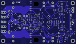
SA2015: using vertical mosfets IXTH80N20L and IXTH48P20P
just sent this to fab. Hopefully no routing errors.
This time a have placed the ground planes on top. The SK76 heatsink can be mounted without isolation washers.
BR, Toni
just sent this to fab. Hopefully no routing errors.
This time a have placed the ground planes on top. The SK76 heatsink can be mounted without isolation washers.
BR, Toni
Attachments

No - I have built only one amp for measurements.Toni, by the way, have you ever put the 200W CFA in a box and compare the sound with your amps?
BR, Damir
BR, Toni
Last edited:
Thx! To which BIAS value /post are you referring? 100 - 150mA for the V-MOSFETs are needed to get good THD results at crossover region. Higher BIAS up to 500mA is possible if you want to get more watts in Class A region. The bias is constant in between 5% from room temperature to > 60-70 degree heatsink temperature.Nice performance, very respectable THD numbers, although the bias current seems a tad on the high side in terms of no signal dissipation, how does the bias track over the operating temp range ?...
BR, Toni
I was mainly referencing/thinking of consumer applications like home theatre where 6 channels of fairly high idle dissipation (assumed at least 100 mA) can really add up to high temps within a chassis/enclosure. Perhaps with Cordell style local output stage error correction one could lower the idle current to say 30 - 50 mA and obtain similar THD numbers ?
#2171
astx is offline astx Austria
diyAudio Member
Join Date: Jan 2011
Location: Tyrol / Austria
Default SA2015: using vertical mosfets IXTH80N20L and IXTH48P20P
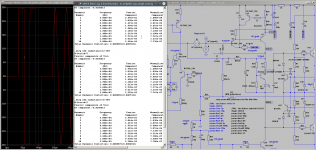
Test sample using 1 pair of IXTH80N20L and IXTH48P20P up und running!
Quick THD+N tests (80k bw) with SOA circuit in situ:
THD+N 20k@100W@8R: 0.0035%
THD+N 20k@200W@4R: 0.0042%
#2171
astx is offline astx Austria
diyAudio Member
Join Date: Jan 2011
Location: Tyrol / Austria
Default SA2015: using vertical mosfets IXTH80N20L and IXTH48P20P
Test sample using 1 pair of IXTH80N20L and IXTH48P20P up und running!
Quick THD+N tests (80k bw) with SOA circuit in situ:
THD+N 20k@100W@8R: 0.0035%
THD+N 20k@200W@4R: 0.0042%
You can go for lower bias but THD will increase especially at crossover region. For the SA2016 using L-MOSFETS I have done some test with very low bias. See table at post#1765
For V-MOSFETs you will need always higher bias to get respectable values. Maybe I have some sparetime to repeat measurements also for SA2015/V-MOSFET variants at low bias currents.
BR, Toni
For V-MOSFETs you will need always higher bias to get respectable values. Maybe I have some sparetime to repeat measurements also for SA2015/V-MOSFET variants at low bias currents.
BR, Toni
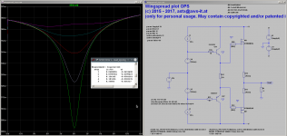
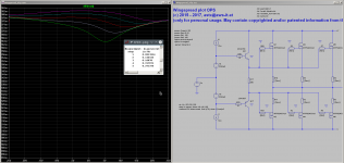
Is the 100mA per device, or total stage bias current?Outputstage linearity versus bias:
A bias not lower as 100mA is recommended for good OPS linearity.
It is per device.Is the 100mA per device, or total stage bias current?
BR, Toni
So the LatFET, single big vertFET and multiple VertFET are all getting close too Borbely's recommendation of >=500mA of output stage bias for FET outputs.
... a good rule of thumb!So the LatFET, single big vertFET and multiple VertFET are all getting close too Borbely's recommendation of >=500mA of output stage bias for FET outputs.
BR, Toni
- Home
- Amplifiers
- Solid State
- 2stageEF high performance class AB power amp / 200W8R / 400W4R