Another question I have is about the dual triode. Obviously they work, but when electrons flow from the cathode(s). how do they "go" to the correct plate?
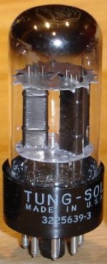
Most twin triodes are 2 separate systems, that share the base, bottle, and heater connections. Notice that each of the plates surrounds the grid and cathode.
Attachments
Construction
Hi,
I get it, so really the plate in the case shown is really a oval containing sleeve for the cathode, then the grid must also then be a smaller containing sleeve with the cathode being inside of both.
That makes sense.
Thank you sir.
Ron
Hi,
I get it, so really the plate in the case shown is really a oval containing sleeve for the cathode, then the grid must also then be a smaller containing sleeve with the cathode being inside of both.
That makes sense.
Thank you sir.
Ron
Sophia 2a3-05
Hi,
I heard back about the OPTs, the primary inductance is 25H.
Is there a way to verify this?
Thanks,
Ron
Hi,
I heard back about the OPTs, the primary inductance is 25H.
Is there a way to verify this?
Thanks,
Ron
Device
Hi,
What do we think about this
More Information Page
Retail 4K can be bought for so much less?
Does any one have one of these?
Thanks,
Ron
Hi,
What do we think about this
More Information Page
Retail 4K can be bought for so much less?
Does any one have one of these?
Thanks,
Ron
You can test it by running 60mA of DC current through the primary and placing a 150k of resistance in series with the winding. Now run a 1kHz sine wave through both primary winding and 150k resistor, I would think if the primary was 25H then it's reactance at 1kHz would be 157k ohms, the sine wave should drop -3db.
Test
Hello Famousmockingbird,
I will get set up to try to do that. My workstation needs a piece of wood on the work surface, it is a glass desk, I have a long power strip along the far edge, my DC power supply, scope, and signal gen are to the left, might need some coaching after a photo post tomorrow. I'll have to post some pictures of the OPTs as I do not have the knowledge to identify the primaries vs the secondaries. Probably running a small current through one side and measuring the other is how to identify, don't want any damage.
I have to say to you ALL and I really mean it, that I am so appreciative of your help, envolvment, coaching, teaching, and patience. As I said before, the world would be a better place with more people like you!!!
Thanks again,
Ron
Question
Hi,
To measure the "DCR" of both windings, how do I do this?
What is DCR?
Maybe I am asking too much, I don't want to impose on any of you nice people.
A guess - direct coupled resistance - but I have no idea.
Thanks,
Ron
Hi,
To measure the "DCR" of both windings, how do I do this?
What is DCR?
Maybe I am asking too much, I don't want to impose on any of you nice people.
A guess - direct coupled resistance - but I have no idea.
Thanks,
Ron
primary DCR is simply the resistance of the primary winding,
set your dmm to ohms and then measure, my OPT measures 80 ohms,
so with 60mA of plate current, this results in 4.8 volts lost...
higher DCR and you have bigger loss...
set your dmm to ohms and then measure, my OPT measures 80 ohms,
so with 60mA of plate current, this results in 4.8 volts lost...
higher DCR and you have bigger loss...
The attached circuit is indeed PP, but so what? It is so much better than 99% out of all "modern" 2A3 circuits that it's not even funny.
I love this design you posted.It's all inductively coupling outside of the first stage with the one .47 coupling cap going into the primary of the phase splitter trafo.
Member
Joined 2009
Paid Member
Hi,
I heard back about the OPTs, the primary inductance is 25H.
Is there a way to verify this?
Thanks,
Ron
Is this necessaey ? Seems to me that you have some nice transformers and output tubes and no need to get distracted by them any further. There's lots to do still to build the amp so maybe decide on the two remaining key items 1- the power supply and 2- the input/driver. Then get ordering the remaining bits!
For a traditional design you'll want tube rectifier supply, choke loaded.
The driver stage could be cascaded 6sN7 as suggested or a single tube such as a triode-wired pentode. There are many proven schematics, which are on the web, less risky than reinventing a design.
Some other reading...
Simon's New Adventures In Hi Fi: Design Of A Single Ended 2A3 Valve Amplifier - Part 1
2A3 SET ? TRIODE LAB
I Never Met A 2A3 Amp That I Didn't Like Article By Editor Joe Roberts From Sound Practices Issue 15
https://web.archive.org/web/20111012095255/http://angela.com/angelamodel91amplifier.aspx
25H will work good with the 2A3. You don't have to measure them but sometimes it's nice to know how matched they are. The DCR is important to know so you can take voltage drop into consideration when designing the power supply.
I wouldn't advise copying a schematc. A two stage amp will be easy enough to design from scratch with the help from everyone on here. At the end of the day you will hold your head higher knowing you didn't just copy a schematic. Don't worry it will sound lovely.
I wouldn't advise copying a schematc. A two stage amp will be easy enough to design from scratch with the help from everyone on here. At the end of the day you will hold your head higher knowing you didn't just copy a schematic. Don't worry it will sound lovely.
Not so good example. from post 76
70V (70V - 1.5V) is too low value of Va for 6SN7. the tubes are voltage devices. 🙂
and for contemporary sources 1.5V of -Ug is too low.
70V (70V - 1.5V) is too low value of Va for 6SN7. the tubes are voltage devices. 🙂
and for contemporary sources 1.5V of -Ug is too low.
Last edited:
@
http://www.diyaudio.com/forums/tubes-valves/289123-2a3-driver-8.html#post4669270
Yes. but acc. to datas for 6N7 mu=35, Ri=11K per section.
One section is just enough?
with sectopns in parallel the same thing about Cdyn is present, this time for input tube, but double. 🙂
And somehow looking at the datas, this tube is main for +Ug region?
But it could set also in -Ug region, at the first site, it is linear with -2V Ug.
that giving room for 4V p-p input signal... 🙂
Attachments
Last edited:
Hi,
I heard back about the OPTs, the primary inductance is 25H.
Is there a way to verify this?
Thanks,
Ron
25Hy is the good value for primary inductance with respect to lower end.
Other words You will have more than good bass. And gives You a room for the lower values of Ck in cathode node 2A3 Rk biasing...
I got the -1db@8Hz with bit more than 22Hy with probably 600ohms generator
the 2A3 is as generator something like this value (see Ri from the datas or calculate using graph method from the exact working point from the graph...)
@
http://www.diyaudio.com/forums/tubes-valves/289123-2a3-driver-8.html#post4669270
Yes. but acc. to datas for 6N7 mu=35, Ri=11K per section.
One section is just enough?
with sectopns in parallel the same thing about Cdyn is present, this time for input tube, but double. 🙂
And somehow looking at the datas, this tube is main for +Ug region?
But it could set also in -Ug region, at the first site, it is linear with -2V Ug.
that giving room for 4V p-p input signal... 🙂
One section isn't enough. Have a look at the curves of each section again at Va=150. Mu/gm.
35/.0015=23,000
The 11k=Ri is for both sections in parallel.
Unlike the others, I disagree with the 25Hy value - it does not need to be this high. 10-15Hy is fine enough for single ended 2a3. There are other important factors to consider too.
For example I take the Tango XE-20s which is a very decent OPT but only has primary impedance of something like ~16 Henries on the 3.5k primary windings (into whatever correct load it is reflected into)
The -3dB low frequency cutoff point can be determined by the following formula:
f = Z/(2*Pi*L)
Z is the primary source impedance (reflected impedance in parallel with the source impedance presented by the tube's plate)
L is the primary inductance.
So lets take for example a 2a3 driving a Tango XE-20s on the 3.5K ohm taps. Lets run the 2a3 at 250V A-K biased at -45V on the grid giving an Rp of 800 ohm, just like in the RCA specs sheet.
Z= (3500 *800)/(3500+800) = 651 ohm
L= 16H
f= 651/(2*Pi*16) = ~6.5 Hz
I think you will agree that a 3db low frequency cut-off of around 10Hz or less is good enough.
So what else is important?
Voltage drop is a factor to look at, as well if there is any HF ringing and how well the transients are handled, so you need to consider DCR, leakage inductance and capacitance.
Very good OPT's will exhibit low DCR, low leakage inductance and low capacitance.
Then of course there is power handling and simple mechanical considerations (i.e. does it vibrate). Then you have to consider layout - how to best position it on your chassis. After all this then you have it really sorted.
Ian
Last edited:
Interesting Component
Hi,
Looking at chokes, I found this
Mercury Magnetics
Has anyone tried them? Seems like a good idea to me from reading that choke changes in the PS make a big difference in sound.
Any thoughts?
Thanks,
Ron
Hi,
Looking at chokes, I found this
Mercury Magnetics
Has anyone tried them? Seems like a good idea to me from reading that choke changes in the PS make a big difference in sound.
Any thoughts?
Thanks,
Ron
Unlike the others, I disagree with the 25Hy value - it does not need to be this high. 10-15Hy is fine enough for single ended 2a3. There are other important factors to consider too.
For example I take the Tango XE-20s which is a very decent OPT but only has primary impedance of something like ~16 Henries on the 3.5k primary windings (into whatever correct load it is reflected into)
The -3dB low frequency cutoff point can be determined by the following formula:
f = Z/(2*Pi*L)
Z is the primary source impedance (reflected impedance in parallel with the source impedance presented by the tube's plate)
L is the primary inductance.
So lets take for example a 2a3 driving a Tango XE-20s on the 3.5K ohm taps. Lets run the 2a3 at 250V A-K biased at -45V on the grid giving an Rp of 800 ohm, just like in the RCA specs sheet.
Z= (3500 *800)/(3500+800) = 651 ohm
L= 16H
f= 651/(2*Pi*16) = ~6.5 Hz
I think you will agree that a 3db low frequency cut-off of around 10Hz or less is good enough.
So what else is important?
Voltage drop is a factor to look at, as well if there is any HF ringing and how well the transients are handled, so you need to consider DCR, leakage inductance and capacitance.
Very good OPT's will exhibit low DCR, low leakage inductance and low capacitance.
Then of course there is power handling and simple mechanical considerations (i.e. does it vibrate). Then you have to consider layout - how to best position it on your chassis. After all this then you have it really sorted.
Ian
Hello
between two OPTs 3K/46H/25W and 3K/29H/10W for application in 2A3 SE How prefer
Τhank you
One section isn't enough. Have a look at the curves of each section again at Va=150. Mu/gm.
35/.0015=23,000
The 11k=Ri is for both sections in parallel.
thanks 🙂
in the datasheets for double triodes usually is given Ri for each section...
in this datasheet is stated as booth sections.
I didnt pay additional attention... sorry.
- Status
- Not open for further replies.
- Home
- Amplifiers
- Tubes / Valves
- 2A3 driver