Or, if you need yet another suggestion: How about a 6N7 http://www.mif.pg.gda.pl/homepages/frank/sheets/021/6/6N7.pdf
It has a u of 35 and plenty of "grunt" and very linear curves. It has a common cathode, so if you want to use both halves independently, you need to have a negative supply to use fixed bias on the grids. Could use a FET follower and take from that negative supply, but that's overkill - hey, this is DIY.
Sheldon
Or, if you need yet another suggestion: How about a 6N7 http://www.mif.pg.gda.pl/homepages/frank/sheets/021/6/6N7.pdf
It has a u of 35 and plenty of "grunt" and very linear curves. It has a common cathode, so if you want to use both halves independently, you need to have a negative supply to use fixed bias on the grids. Could use a FET follower and take from that negative supply, but that's overkill - hey, this is DIY.
I second the 6N7. I use it in my 6HJ5 amp . I use a CCS as the plate load and it works beautifully. Lots of gain, low enough rp and plenty of current. As stated it's very linear, I use both triodes in the envelope in parallel.
http://www.diyaudio.com/forums/tubes-valves/288856-6hj5-set.html
Info
Hello,
Wow!! I am overwhelmed with the support for you all...
Link to tubes
Emission Labs - 2A3 tube data sheet. Mesh Version.
Link to OPTs
http://www.sophiaelectric.com/pages/parts/2a3_opt.htm
Input transformer PDF attached
thanks,
Ron
Hello,
Wow!! I am overwhelmed with the support for you all...
Link to tubes
Emission Labs - 2A3 tube data sheet. Mesh Version.
Link to OPTs
http://www.sophiaelectric.com/pages/parts/2a3_opt.htm
Input transformer PDF attached
thanks,
Ron
Attachments
I don't want to damage costly mesh plate O/P tubes. IMO, better a little less power and have long lasting 2A3s. There will be no positive grid current regime in this build.
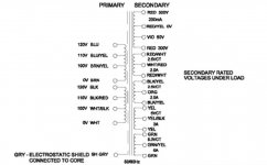
Lots of good info. is contained in the Hammond 302AX power trafo wiring diagram.
The 2.5 VAC windings have center taps. Those CTs allow a builder to dispense with hum balance trim potentiometers. For the most part, other than single 2A3 "finals" in each channel, you will follow the schematic of the PSE amp, insofar as signal topology is concerned. Connect the ends of the 2.5 VAC windings to the 2A3 filaments. Connect the 100 μF./1 Kohm bias networks to the CTs and ground.
Remember what I said about mix/match and pick/choose. The "Level 5" amp provides the B+ PSU. 😉 Use an inexpensive Sovtek 5AR4 as the rectifier, but install the SS diode tweak, according to the uploaded diagram. Use UF4007s, instead of 1N4007s, as they are inherently less noisy.
Attachments
Here is where I am at, I have (1) - 302ax, (2) Sophia Electric 2a3-05 OPT, (2) - EML 2a3's. (My kids got together this holiday season).
I almost choked when I saw the prices of those tubes!!! You have some very nice children 🙂
I wouldn't push those 2A3's. For your first build I would suggest do something simple and get the basics right anyway. Good layout and lead dress, proper grounding etc... I am thinking a two stage design, cathode biased. Use a 220k grid leak resistor and that will give you plenty of choices for drivers, anything with a plate resistance of 10k and under is fine. Spend the time on the power supply and get that right it will make a big difference.
I am working on something for you and will add it to the list of schematics for you to pick from.
Kids
Hi,
Yeah, they went a little crazy. Being sick makes them treat me differently. I hope it gets better with time. I'm learning to keep my mouth shut around them as they get carried away. That's why I want to really do this right. It will be fun when I get to the chassis and such to really dig in a do a good job.
Thank you all for your help!
You are a good bunch of folks.
Ron
Construction
Hi,
I surely won't be putting those tubes in until everything is as good as can be and checked out with some other tubes. And as you say, the power supply has to be a solid foundation. Clean as it possibly can be. It will be a good time as each portion of the build can be dissected and made correctly. But that's the fun part of doing anything like this. And maybe meeting some nice folks along the way.
Thanks for your help!
Ron
FWIW, i am using a 90db FS speakers and sound is sufficient, the kick drums are a delight to hear....
Hi,
I surely won't be putting those tubes in until everything is as good as can be and checked out with some other tubes. And as you say, the power supply has to be a solid foundation. Clean as it possibly can be. It will be a good time as each portion of the build can be dissected and made correctly. But that's the fun part of doing anything like this. And maybe meeting some nice folks along the way.
Thanks for your help!
Ron
250 volts plate and 60mA operating point works very well for me....
Hi,
I surely won't be putting those tubes in until everything is as good as can be and checked out with some other tubes. And as you say, the power supply has to be a solid foundation. Clean as it possibly can be. It will be a good time as each portion of the build can be dissected and made correctly. But that's the fun part of doing anything like this. And maybe meeting some nice folks along the way.
Thanks for your help!
Ron
A good, low cost, way to check your setup out is by using triode wired 6AV5s. Other than basing and filament voltage, the 6B4 is the same as the 2A3. When Sylvania got a contract for 6B4 military spares, they fulfilled it by internally triode wiring 6AV5s. 😀 "Monkey see, monkey do."
Last edited:
Info
Hi,
That's the kind of super info that I need and is great to share. I really appreciate it. I keep my eyes open for some. Can't wait to start the components discussion. That will be fun. Just something like the chassis plate material choice will be interesting. Copper anyone? Didn't the older Japanese units have that?
Thanks all!
Ron
when setting up...i will put a higher than "required" cathode resistor on the 2A3,
that way the tube is not stressed so much.....
i will take note of the OPT primary dc resistance, take that into consideration in adjusting for the final psu configuration...
the psu B+ is the sum of the plate voltage, cathode voltage and OPT primary resistance and any other resistors in series....
that way the tube is not stressed so much.....
i will take note of the OPT primary dc resistance, take that into consideration in adjusting for the final psu configuration...
the psu B+ is the sum of the plate voltage, cathode voltage and OPT primary resistance and any other resistors in series....
Copper anyone?
Strength, corrosion, and/or finish durability will be a problem. Stick to aluminum, of adequate thickness. While many a project has been built with a metal plate and a wood frame, an interesting low cost option is a thick walled, deep, commercial kitchen, aluminum, baking pan. A number of finishing techniques are available, for aluminum. If a "house" is available and the budget permits, powder coating can be an excellent choice. "Hammerite" brand hammer tone paint is a fairly easy, modest cost, method.

You can imagine like a additional load to Ra+Rg driver already sees in DC mode.I just had a look at the 2A3 datasheet and the miller capacitance isn't all that high at 80pF. For a sine wave of 45v peak @ 20kHz you only need .45mA of current.
(gain goes down, driver loadline more steep- increases treble thd)
C₄ and C₃ seem far too large, and will just end up amplifying wow, flutter and rumble. Using
F–3db = ½πRC
F–3db = 1/(6.283 × 4.7×10³ × 1000×10⁻⁶)
F–3db = 0.034 Hz
C₁/R₁ is around 0.73 Hz
C₂/R₅ is around 0.73 Hz, also
C₅/R₄ introduces a high-cut filter at about 72 Hz
C₆/R₈ rolls off below 34 Hz
So no, I'm not seeing a need for deeeeeeep subsonic cathode bypassing. Pointless overkill.
GoatGuy
PS: I like a design point where the lowest 'spec' frequency is divided by 2N or twice the number of stages. There are 3 stages in this amp; 20 Hz / (2 × 3) = 3.33 Hz. Now, 'do' all the capacitors to fit that.
R₁ (220 kΩ) - C₁ = 0.22 μF
R₅ (220 kΩ) - C₂ = 0.22 μF
R₄ (22 kΩ) - C₅ = unchanged (it must be 72 Hz for a reason?)
R₈ (100 kΩ) - C₆ = 0.47 μF
R₂ (4.2 kΩ) - C₄ = 15 μF
R₂ (4.2 kΩ) - C₄ = 15 μF
With capacitance values chosen per closest higher standard [10, 15, 22, 33, 47, 68] (20%) decade sequence.
Last edited:
You can imagine like a additional load to Ra+Rg driver already sees in DC mode.
(gain goes down, driver loadline more steep- increases treble thd)
Hi, Yes I see.
Question: The Xc of an 80pF cap @ 20kHz would be roughly 100k. Now to the driver that would be in parallel with the 2A3 Rg? The way I picture it is that if you had a 220k Rg and the 100k was in parallel, at 20kHz the driver now sees a 68k load? For the 10x impedance mismatch rule of thumb you would be looking at a driver with an output impedance of <6k?
And +1 for an Aluminum chassis.
Last edited:
Another problem is that Miller cap will "soften" signal edges with more force, than with a low ri driver used. (square wave response; we can look at it also as low pass filter)
I´m afraid this is happening to me, replaced just tube, rest is same. (ri 6x less)
I´m afraid this is happening to me, replaced just tube, rest is same. (ri 6x less)
- Status
- Not open for further replies.
- Home
- Amplifiers
- Tubes / Valves
- 2A3 driver