Hehe, yea, that part i was quite convinced that i got decent results on this time 🙂Check the impedance graphs yourself, but they look much more realistic than before. 🙂
I did them all 1m measured within milimeters.I would do the far field measurements no further than1m though. 6ms ~= 2 meters I think. 🙂 The response curves for the individual drivers look really good.
The speaker was a few centimeters from the wall and angled towards the listening position in the sofa.I'm surprised you aren't getting more of a lift from the wall for the woofer though. I thought for sure placing it against the wall would improve the response somewhat.
I have phase in all files 🙂Anyway, they look great. Make sure you include phase in your impedance and fr if at all possible. Measure 3' from listening position and you should be ready to create a crossover in XSim. Er, wait, did you do driver distance already?
"Woofer wall - listening position" is 1m from the speaker in the listening position direction if thats what you mean? 🙂
I haven't done driver distance yet, will do soon 🙂 I can use the far field measurements for that right? I know you mentioned in your blog about 1V level but i guess 2,83V would work as well? 🙂
About combining near and far-field measurements, how do you usually go about that?
Yes, any signal that gets you above the noise floor is fine. In your case you can do everything at once with a 2.83V signal. 🙂 That tweeter is pretty robust.
Oooh, 6mSeconds was the gating? I thought it was the delay. 🙂
Best,
Erik
Oooh, 6mSeconds was the gating? I thought it was the delay. 🙂
Best,
Erik
Hehe, yea, that part i was quite convinced that i got decent results on this time 🙂
I did them all 1m measured within milimeters.
The speaker was a few centimeters from the wall and angled towards the listening position in the sofa.
I have phase in all files 🙂
"Woofer wall - listening position" is 1m from the speaker in the listening position direction if thats what you mean? 🙂
I haven't done driver distance yet, will do soon 🙂 I can use the far field measurements for that right? I know you mentioned in your blog about 1V level but i guess 2,83V would work as well? 🙂
About combining near and far-field measurements, how do you usually go about that?
Thanks 🙂These measurements look much better. You have done a great job with your new microphone and amp.
You haven't mentioned it but did you calibrate your soundcard?
Robert
No i didn't but ofc i should have right?
 I will never finish this 😛
Is ARTA's calibration steps all that i need to do?
Attachments
No i didn't but ofc i should have right? I will never finish this 😛
Don't give up. You are doing great. I am learning too from following your journey.
Is ARTA's calibration steps all that i need to do?
I use REW which allows you to produce a calibration file to eliminate any non-linearity in the frequency response of the sound card. If you don't do this any variation in the sound card response will be added to your speaker measurements. This might or might not be a problem depending how good your sound card is.
I have never used it so I don't know if you can do this with ARTA. Maybe someone else can help with this.
Robert
Don't worry, i never give up! 😀 I just had alot to do the last few days so i didn't have time to play with this.
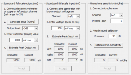
Im playing around with the calibration, i have no issues calibrating the sound card but i struggle a bit when it comes to "Microphone calibration"(Page 42):
http://www.artalabs.hr/AppNotes/ARTA Handbook Version 2.4 English.pdf
The box in ARTA states "Microphone sensitivity (mV/Pa)", is this something that i need to worry about if i don't care about absolute SPL? I guess that i don't care about that atm? HELP!!
Btw, i found a calibration file for WM61A:
http://www.holmacoustics.com/downloads/MicrophoneCalibration/Mic_WM61A.cal
http://www.diyaudio.com/forums/soft...lse-measuring-frequency-impulse-response.html
I know that this is not the exact calibration of my specific microphone but i guess its better than running without?
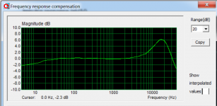
I added the microphone WM61A calibration data to ARTA and i got this graph showing the calibration curve:

Attachments
Last edited:
Okey, today i did another set of measurements with some further changes.
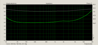
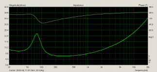
Impedance:
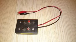
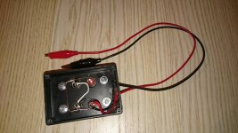
-I constructed a simple measurement box to get it all soldered in place and eliminate some of the resistance of the lousy cables i was using. Now i could lower the cable resistance to 0.9ohm.
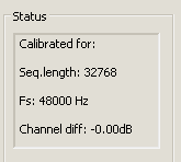
-I also did a calibration in LIMP
Now im finally pleased with the impedance curves, if i compare the Tweeter curve to the one on the spec sheet http://spicaspeakers.com/pdfs/peerless-801730.pdf it is close to identical 😀
Calibration:

Tweeter:

Woofer:

Impedance:
-I constructed a simple measurement box to get it all soldered in place and eliminate some of the resistance of the lousy cables i was using. Now i could lower the cable resistance to 0.9ohm.
-I also did a calibration in LIMP
Now im finally pleased with the impedance curves, if i compare the Tweeter curve to the one on the spec sheet http://spicaspeakers.com/pdfs/peerless-801730.pdf it is close to identical 😀
Calibration:
Tweeter:
Woofer:
Attachments
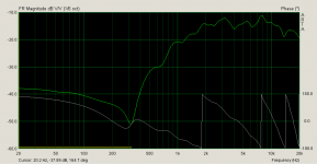
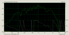
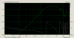
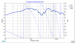
FR farfield measurements was also changed by:
-Calibration of output and input in ARTA(ignored mic sensitivity)
-Added the generic WM61A mic calibration file mentioned above.
-1/6 oct smooting
Farfield measurements at 2,83V gate started at 6,125ms, 1m. 102cm from floor.
Tweeter:

Woofer:

Tweeter+Woofer:

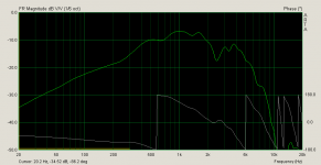
Woofer wall:

Woofer wall extended gate for farfield down to 40dB just as a test:

-Calibration of output and input in ARTA(ignored mic sensitivity)
-Added the generic WM61A mic calibration file mentioned above.
-1/6 oct smooting
Farfield measurements at 2,83V gate started at 6,125ms, 1m. 102cm from floor.
Tweeter:
Woofer:
Tweeter+Woofer:
Woofer wall:
Woofer wall extended gate for farfield down to 40dB just as a test:
Attachments
-
 2016-02-21 15_19_50-Smoothed frequency response (Untitled).png34.3 KB · Views: 180
 -
 2016-02-21 15_18_04-Smoothed frequency response (Untitled).png32.4 KB · Views: 182
 -
 2016-02-21 15_53_37-Smoothed frequency response (Untitled).png32.6 KB · Views: 177
 -
 2016-02-21 15_55_16-Smoothed frequency response (Untitled).png35.6 KB · Views: 181
 -
 2016-02-21 15_14_40-Smoothed frequency response (Untitled).png32.4 KB · Views: 178
Last edited:
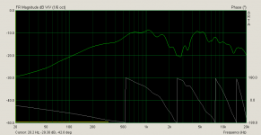
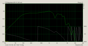
FR farfield measurements was also changed by:
-Calibration of output and input in ARTA(ignored mic sensitivity)
-Added the generic WM61A mic calibration file mentioned above.
-1/6 oct smooting
-Lowered voltage to 0,226V due to clipping.
Nearfield measurements at 0,226V gate started at 6,125ms, 0,4cm from driver.
Tweeter:

Woofer:

-Calibration of output and input in ARTA(ignored mic sensitivity)
-Added the generic WM61A mic calibration file mentioned above.
-1/6 oct smooting
-Lowered voltage to 0,226V due to clipping.
Nearfield measurements at 0,226V gate started at 6,125ms, 0,4cm from driver.
Tweeter:
Woofer:
Attachments
And my new little impedance tester, including a 100ohm 1% 1W resistor.


I actually think i might have something decent here. Next thing is to combine nearfield and farfield somehow 😛 Then maby, just maby, we can continue actually designing a crossover for this godforsaken speaker 😀
I actually think i might have something decent here. Next thing is to combine nearfield and farfield somehow 😛 Then maby, just maby, we can continue actually designing a crossover for this godforsaken speaker 😀
Attachments
Last edited:
Very nice work!
So a DIYer finally explained to me why people even do nearfield measurements for crossover design. It's to get accurate phase and crossover slopes in the bass where it's unlikely you could do so otherwise. It never occurred to me because all my designs are essentially 2 way systems with crossovers around 2kHz.
If you had a 3-way with a woofer crossing into the mid at 300 Hz or so then you'd need to go through the more complicated measurement steps.
Barring that, there's no reason to go through that exercise. Get the far-field measurements we discussed, and you'll do great. It may even be less prone to error and mistakes since it's far simpler.
Best,
Erik
And my new little impedance tester, including a 100ohm 1% 1W resistor.
I actually think i might have something decent here. Next thing is to combine nearfield and farfield somehow 😛 Then maby, just maby, we can continue actually designing a crossover for this godforsaken speaker 😀
Last edited:
Thanks 🙂Very nice work!
So a DIYer finally explained to me why people even do nearfield measurements for crossover design. It's to get accurate phase and crossover slopes in the bass where it's unlikely you could do so otherwise. It never occurred to me because all my designs are essentially 2 way systems with crossovers around 2kHz.
If you had a 3-way with a woofer crossing into the mid at 300 Hz or so then you'd need to go through the more complicated measurement steps.
Barring that, there's no reason to go through that exercise. Get the far-field measurements we discussed, and you'll do great. It may even be less prone to error and mistakes since it's far simpler.
Best,
Erik
As far as i have understood it you more or less have to take near and farfield measurements to eliminate echo from the room and get valid data across the entire frequency range? With ARTA you set the gate to before the echos reach the mic and therefore you get a more clean reading. The downside is that the farfield measurement is not valid in the lower parts of the frequencies with the narrow gate that you will be able to get form indoors. Therefore you take near-field and combine them.
I understand your point that our crossover will be around 2kHz and therefore the lower range is not that interesting, but as im not getting much bass i figured that it would be good to get some valid measurements in the lower range as well? About "flattening the woofers response" with baffle step compensation? 🙂
The old program i used, "TombStone", did not use this impulse and, as far as i understand it, therefore included all noice from echos in the room in the measurement?
EDIT:
A quote from the guide that "5th element" posted:
measurement guide
"Now to a certain degree this is all we need to do decent crossover work. The far-field measurements have given us accurate data down to a low enough frequency to allow us to simulate well enough around the proposed crossover frequency of 2kHz. The far-field measurements have also given us accurate measurements of cabinet diffraction too so we can attempt to account for it in the crossover. The only thing we haven't yet got an accurate representation of is the lower end of the mid/basses response and the complete effect of baffle-step.
If one were designing an active two way system they could stop here. Baffle-step compensation is a relatively easy thing to compensate for and is accomplished by using a simple shelving network and this can be accurately implemented using mathematics alone – ie we don't actually need to measure it. Indeed when combining a near-field response with a far-field one, we don't actually measure baffle-step we simply tack on a best guess simulation. As mentioned before the far-field measurement contains all the useful phase data necessary for accurate crossover simulation and we do not wish to alter this, so if we want to add in the low frequency data we simply replace the low frequency portion of the far-field measurement with the low frequency portion of a near-field measurement/simulation. This leaves the high frequency phase data in tact so we can still simulateaccurately."
Kinda says the same thing as you 😀 I have already done all the farfield measurements and i don't think that i can improve them alot from what i posted in #209?
Last edited:
Great work.
Thanks for posting the link for the WM61A mic calibration file. I hadn't seen that before. I will use it for my measurements.
One thing I noticed is that the shape of the calibration file curve is very close to the frequency response for the microphone in Fig III of John Conover's article but the level at 15kHZ is about 3dB up in Fig III and 6dB up in the calibration file.
Which one is best to use?
Have you decided how you will blend the Near and Far-field measurements?
A piece of software that might help you is The FRD Response Blender and Minimum Phase Extractor by Charlie Laub and Jeff Bagby.
I have played around with it a bit and it looks good to me.
Regards
Robert
Thanks =)Great work.
Thanks for posting the link for the WM61A mic calibration file. I hadn't seen that before. I will use it for my measurements.
One thing I noticed is that the shape of the calibration file curve is very close to the frequency response for the microphone in Fig III of John Conover's article but the level at 15kHZ is about 3dB up in Fig III and 6dB up in the calibration file.
Which one is best to use?
Have you decided how you will blend the Near and Far-field measurements?
A piece of software that might help you is The FRD Response Blender and Minimum Phase Extractor by Charlie Laub and Jeff Bagby.
I have played around with it a bit and it looks good to me.
Regards
Robert
Glad you like the link, it was the only working link i found to a cal file for the WM61A. About the FR in Fig III on John's page; its quite different to the data from Holm and i have no clue why that is. I decided to trust the calibration data from Holm since its also includes the phase data.
I haven't descided how to go on with merging the measurements, or even if i will/need to do that.
I was actually playing around with that XLS file when you posted your comment 😀 I will have to look at it some more to understand all of it though, but it seems to work okey. 🙂
Yes, what 5th element is saying is the same thing. You just have to accept the lumps in the FR below 300 and visually smooth them out, ignoring the dips and peaks.
The truth is we listen (most of us) way out in the far-field, so that will give you the most true measurements of speaker+room+crossover results if we measure by what you'll experience (arguably just at 1 location in your room though). It's a bugger to design woofers (~= 300Hz or less) to integrate with a mid that way though, so the extra efforts and Bagby's Blender spreadsheet become worth while.
 For us brilliant people who don't step out of 2 way systems however it's unnecessary work. 🙂
Best,
Erik
The truth is we listen (most of us) way out in the far-field, so that will give you the most true measurements of speaker+room+crossover results if we measure by what you'll experience (arguably just at 1 location in your room though). It's a bugger to design woofers (~= 300Hz or less) to integrate with a mid that way though, so the extra efforts and Bagby's Blender spreadsheet become worth while.
For us brilliant people who don't step out of 2 way systems however it's unnecessary work. 🙂 Best,
Erik
Haha, i will just have to accept that i don't have any valid data below 300Hz then 😀Yes, what 5th element is saying is the same thing. You just have to accept the lumps in the FR below 300 and visually smooth them out, ignoring the dips and peaks.
The truth is we listen (most of us) way out in the far-field, so that will give you the most true measurements of speaker+room+crossover results if we measure by what you'll experience (arguably just at 1 location in your room though). It's a bugger to design woofers (~= 300Hz or less) to integrate with a mid that way though, so the extra efforts and Bagby's Blender spreadsheet become worth while.
I'll probably never design anything other than 2way speakers anyway and keep being brilliant😉
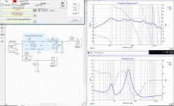
Okey, so i finally started to play around lite in XSim. First i started to find the correct woofer delay. Last time i did this i had to invert the polarity of the woofer and +0,77in delay.
This is what i got without inverting polarity and adjusting woofer delay to +1,32in 🙂
One question, in the delay adjustment above i used the woofer+tweeter data from the middle of the room and impedance, i figure thats correct but should i then change to the woofer data with the speaker in listening position(next to wall) for the remainder of the crossover design?
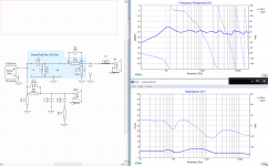
This is your crossover design unmodified but the following things changed:
New woofer(wall)+tweeter FRD files valid 300Hz+
New impedance ZMA files
Woofer delay no longer inverted and delay adjusted to +1.32in
Mod sensitivity changed from +20dB to 0dB on woofer and tweeter.
Changed output to 1W to match the measurements 🙂
Attachments
eriksquires: I played around a little bit more adding some parts of your initial crossover design to the XSim project you uploaded. I also tuned some components with the goal of getting as close to the -35dB line as possible. I still have a dip in 4-6kHz that i don't know how to get rid of though.
I also removed the phony components in the tweeter circuit, i figured that they were unnecessary now when i have the correct impedance curve for the tweeter?
I also added back R5 to correct impedance, but i don't know how low i can set this, the lower the value of R5 the straighter the impedance curve but the lower the impedance, what is my goal here?
Attachments
Very nice work! I think the overall design looks fairly good. I might say it's a litte bright, but you can adjust that by changing the speaker toe-in (left to right angle relative to your head).
The goal of the impedance equalizer is to keep the PEAKS from being outrageous (30 ohms or more) without lowering the impedance too much (1 Ohm or less change preferred). Staying above 4 Ohms is important, especially with most receivers. If you use a parallel resistor the usual values range from 60 to 100 Ohms. It's main use is for tube amps but also to ensure you don't get ultrasonic oscillations. Power stealing events that you can't hear directly. It really should be the very last thing you worry about in crossover design.
Yes, the phony components are not needed now that you have real Z (impedance) data. They were just there to assist with the modelling. Like masking tape you put on a floor to help understand where the bed should go. 😀
One more thing to check is the inverted tweeter response. Invert the tweeter and you should get a deep and symmetrical null. 10 dB or more, but also it should be a nice smooth dip, not a ragged valley.
eriksquires: I played around a little bit more adding some parts of your initial crossover design to the XSim project you uploaded. I also tuned some components with the goal of getting as close to the -35dB line as possible. I still have a dip in 4-6kHz that i don't know how to get rid of though.
I also removed the phony components in the tweeter circuit, i figured that they were unnecessary now when i have the correct impedance curve for the tweeter?
I also added back R5 to correct impedance, but i don't know how low i can set this, the lower the value of R5 the straighter the impedance curve but the lower the impedance, what is my goal here?
Last edited:
- Status
- Not open for further replies.
- Home
- Loudspeakers
- Multi-Way
- 2 Way speakers - Suggestions on improvements?