One chart I'd like to see is the tweeter and woofer FR with phase. Not (Driver Only). I want to see them with the crossover, but I'd like to see how the phase matches up.
Thanks 🙂Very nice work! I think the overall design looks fairly good. I might say it's a litte bright, but you can adjust that by changing the speaker toe-in (left to right angle relative to your head).
Is it to bright when its flat? Or am i missing something? But as you say its quite simple to correct by just moving the speaker 🙂
Okey, i think that R5 at 20ohm looks good, it just reduces the peaks without reducing overall impedance to much 🙂The goal of the impedance equalizer is to keep the PEAKS from being outrageous (30 ohms or more) without lowering the impedance too much (1 Ohm or less change preferred). Staying above 4 Ohms is important, especially with most receivers. If you use a parallel resistor the usual values range from 60 to 100 Ohms. It's main use is for tube amps but also to ensure you don't get ultrasonic oscillations. Power stealing events that you can't hear directly. It really should be the very last thing you worry about in crossover design.
Haha, great explination 😀 They are gone now then 🙂Yes, the phony components are not needed now that you have real Z (impedance) data. They were just there to assist with the modelling. Like masking tape you put on a floor to help understand where the bed should go. 😀
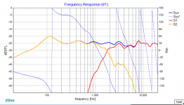
Hum, okey? Lets see then:One more thing to check is the inverted tweeter response. Invert the tweeter and you should get a deep and symmetrical null. 10 dB or more, but also it should be a nice smooth dip, not a ragged valley.
Tweeter inverted polarity and R5 adjusted to 20ohm
Attachments
Hum, something like this?One chart I'd like to see is the tweeter and woofer FR with phase. Not (Driver Only). I want to see them with the crossover, but I'd like to see how the phase matches up.
Attachments
R5 is too small for impedance EQ. Take it out until you are 100 % done. Really you want the highest value R that will do the job, not the lowest. Leaving your impedance peaks around 20 Ohms is fine.
For now, take it out or you end up futzing with it every time you adjust something.
Best,
Erik
For now, take it out or you end up futzing with it every time you adjust something.
Best,
Erik
Yes, but remove system phase, add individual driver phase. 🙂 I would like to see the phase for the yellow and red curves. Blue not really right now.
Hum, something like this?

Okey, i've removed it until later =)R5 is too small for impedance EQ. Take it out until you are 100 % done. Really you want the highest value R that will do the job, not the lowest. Leaving your impedance peaks around 20 Ohms is fine.
For now, take it out or you end up futzing with it every time you adjust something.
Best,
Erik
Now i found out how to add the phase curve 😀Yes, but remove system phase, add individual driver phase. 🙂 I would like to see the phase for the yellow and red curves. Blue not really right now.
Attachments
It's not exactly spot on, but the phase matches beautifully before and after the transition. 🙂
What I'm concerned about really is that valley in response you have around 5-6kHz. Try muting the woofer to see if that goes away. If it does, it is worth doing a little more to the woofer's filter to help the valley disapear.
There are a couple of things to try to do about the phase matching and the valley. Play with the values of the Zobel on the woofer, you could probably get better rolloff and better phase matching at the crossover point.
You can try this by watching the phase plots line up, or inverting the tweeter and watching the null deepen.
Another, similar approach is to add a notch filter for that plateau in the woofer. The Tune is wonky though, you should use single digit numbers until you get close. Otherwise the up/down arrows have too fine a gradient.
Best,
Erik
Okey, i've removed it until later =)
Now i found out how to add the phase curve 😀

Last edited:
Muting the woofer does nothing to the valley, neither does playing with the values of the Zobel. But by adjusting Zobel i managed to get a little better phase machup before the crossover:It's not exactly spot on, but the phase matches beautifully before and after the transition. 🙂
What I'm concerned about really is that valley in response you have around 5-6kHz. Try muting the woofer to see if that goes away. If it does, it is worth doing a little more to the woofer's filter to help the valley disapear.
There are a couple of things to try to do about the phase matching and the valley. Play with the values of the Zobel on the woofer, you could probably get better rolloff and better phase matching at the crossover point.
You can try this by watching the phase plots line up, or inverting the tweeter and watching the null deepen.
Another, similar approach is to add a notch filter for that plateau in the woofer. The Tune is wonky though, you should use single digit numbers until you get close. Otherwise the up/down arrows have too fine a gradient.
Best,
Erik
About the notchfilter, i could not get something decent here. Ill have to get some sleep now but i'm attaching the project here so you can play around with it if you have time? 🙂
Attachments
Oddly enough I got the XSim files, and the impedance data was included but not the FR. Can you attach those too?
Erik
Erik
Oddly enough I got the XSim files, and the impedance data was included but not the FR. Can you attach those too?
Erik
Strange!
Here is the FRD files, i used:
"tweeter farfield.frd"
"woofer farfield wall.frd"
Attachments
Ok, the problem is that your original FRD files are 0 referenced! I wasnt' looking low enough. Check out this version. You get more overall output by reducing the coil on woofer.
I used the "farfield" frd files for the Xover, you may need to reload it. If you can set them to actual SPL levels it would be easier.
Added optional notch filter to tweeter. I'd say listen and add only if needed. Same thing for C3.
Best,
Erik
I used the "farfield" frd files for the Xover, you may need to reload it. If you can set them to actual SPL levels it would be easier.
Added optional notch filter to tweeter. I'd say listen and add only if needed. Same thing for C3.
Best,
Erik
Attachments
Last edited:
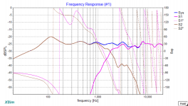
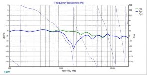
Here are some pretty pics to go along with that. First we have the FR, showing the normal and the inverted tweeter. This is using my own personal blended house curve. I suggest you start with this first, and adjust the tweeter level to taste afterwards by adjusting R3.

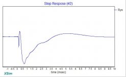
What's odd though is the step response. It shows that the "normal" graph has both drivers tweeter inverted! 😀 That's fine, so long as you wire it right. 🙂 You may want to re-measure after wiring to make sure you got this part right.

The step and phase aren't 100% perfect, but they are very very good.
Lastly, check out how completely easy to drive this speaker will be

The speaker stays above 5 Ohms at all places, a cakewalk for when you get to using Tube amps. 🙂
Not bad I say.
Erik
What's odd though is the step response. It shows that the "normal" graph has both drivers tweeter inverted! 😀 That's fine, so long as you wire it right. 🙂 You may want to re-measure after wiring to make sure you got this part right.
The step and phase aren't 100% perfect, but they are very very good.
Lastly, check out how completely easy to drive this speaker will be
The speaker stays above 5 Ohms at all places, a cakewalk for when you get to using Tube amps. 🙂
Not bad I say.
Erik
Attachments

Last edited:
I'm sorry, I think I may have gotten carried away and done parts you wanted to do, and may have prevented you from learning as much as you could have from this experiment.
Well, you can still try to improve the phase matching, it's not perfect as the phase and step responses show. On the other hand, it will only be perfect exactly when your head is on tweeter axis. 🙂
Another thing to try is doing 30 degree off axis FRD measurements. This will give you a good idea of how the speaker will sound when your not exactly between them. A step I avoid being friendless. Only the Throne needs good sound here.
Once you are done tweaking the schematic to taste, there are some further steps.
- Convert part values to real one's.
- Go to your favorite parts shop (like Parts Express) and enter real DCR's for the inductors. Jantzen specs are usually dead-on.
- Set amp to 20 Watts, and examine the wattage of the resistors in the tweeter section. You'll want to make sure your resistors all exceed the maximum wattage.
- Set Amp to 100 Watts and repeat for woofer.
Best,
Erik
Last edited:
Haha, no problem. I didn't find the graphs at first as well when i first got them into XSim.Ok, the problem is that your original FRD files are 0 referenced! I wasnt' looking low enough. Check out this version. You get more overall output by reducing the coil on woofer.
I used the "farfield" frd files for the Xover, you may need to reload it. If you can set them to actual SPL levels it would be easier.
Added optional notch filter to tweeter. I'd say listen and add only if needed. Same thing for C3.
Best,
Erik
Since i dont have a calibrated mic i don't really know the SPL of the mic measurements right? 🙂
I when i come around to actually start building the crossover i will remember this and remove it if its unessesary 🙂
This looks totally awesome!! Your personal housing curve sounds like i great start! I will probably love it 😀Here are some pretty pics to go along with that. First we have the FR, showing the normal and the inverted tweeter. This is using my own personal blended house curve. I suggest you start with this first, and adjust the tweeter level to taste afterwards by adjusting R3.
What's odd though is the step response. It shows that the "normal" graph has both drivers tweeter inverted! 😀 That's fine, so long as you wire it right. 🙂 You may want to re-measure after wiring to make sure you got this part right.
The step and phase aren't 100% perfect, but they are very very good.
Lastly, check out how completely easy to drive this speaker will be
The speaker stays above 5 Ohms at all places, a cakewalk for when you get to using Tube amps. 🙂
Not bad I say.
Erik
It would probably be good to get a bunch of different values for R3 to play around with then?
I honestly don't understand what you talk about regarding the step response and "both drivers tweeter inverted"? 😕 😱
I took a look at the phase and it looks prittey darn good!
You are killing me here! Now i sooner or later will have to play around with tubes just to experiense it when i have such great speakers for tubes 😉 😀
You are verry much forgiven for getting carried away! I feel like its good for me to actually get something built to start adjusting my ears to "listingen to the curves" and connect the effects of a curve to some real life sound/music!I'm sorry, I think I may have gotten carried away and done parts you wanted to do, and may have prevented you from learning as much as you could have from this experiment.
Well, you can still try to improve the phase matching, it's not perfect as the phase and step responses show. On the other hand, it will only be perfect exactly when your head is on tweeter axis. 🙂
Another thing to try is doing 30 degree off axis FRD measurements. This will give you a good idea of how the speaker will sound when your not exactly between them. A step I avoid being friendless. Only the Throne needs good sound here.
Once you are done tweaking the schematic to taste, there are some further steps.
- Convert part values to real one's.
- Go to your favorite parts shop (like Parts Express) and enter real DCR's for the inductors. Jantzen specs are usually dead-on.
- Set amp to 20 Watts, and examine the wattage of the resistors in the tweeter section. You'll want to make sure your resistors all exceed the maximum wattage.
- Set Amp to 100 Watts and repeat for woofer.
I will probably sit outside of the perfect sweetspot of the speakers quite often even if i will try to sit in the throne as often as possible 😀 Since im not lonley at home it might be a good idea to do as you suggest and measure at 30degrees to see that the crossover behaves decentley there aswell?
After the possible tweeking and corrections that might be needed to make them sound decent at 30 degrees i will start going into real life components! Are you recommending Jantzen for caps and inductors? Something specific to look for in resistors? 🙂 After that i will enter it all into XSim and look for changes that may have occured.
One ting that confuses me is that i should check the wattage of the resistors in tweeter circuit at 20W but in the woofer at 100W, souldn't tweeter resistors be able to coope with that wattage as well?
Just as a sidenote, about the lower freequencies and bass response of the speakers, do you think that i will experience a better feeling there since the lack of it is almost total at the moment? Also, playing around with the glasswool in the speaker, is that something we will leave for later or would it be worth doing now?
Thanks again for all help this far! I think this will be awesome when its done! 😀
I would not invest in that notch filter unless you want to. 🙂 Yes, for R3 try that value and a few smaller, or buy 3 x 1 Ohm resistors, then you can use jumpers to play around with the value until you like it. 🙂
Usually the peaks in the step response goes positive. In this case they both go negative, showing that either your microphone or your speakers was inverted when measuring. Being consistent is 1,000,000 more important than absolute direction, but it would still drive me a little crazy. 😀
As for resistor wattage..... power in music is not equal at all octaves. It's very much bass heavy, so the power needed in the tweeter is around 1/5th (big rule of thumb!) to 1/10th what the woofer will be exposed to.
The glass wool can increase the virtual size of the cabinet, lowering the Q (the bump at the bottom) up to around 15%. Try this with WinISD. Grab a typical driver, and simulate it in an ideal cabinet, then try increasing the volume by 15%, and you'll see what happens. 🙂
If you actually feel resonances at the sides of the cabinet, a better material is the multilayer version of Sonic Barrier.
I've never heard Jantzen Cross caps, but many really like them. Their coils are top notch. For resistors, I love mills for being relatively inexpensive and small for the wattage. My usual recommendation of caps and resistors to start with are Mundorf MKP and Mills. Mundorf MKP's are very good, and the price is in line with the value of your tweeter.
Stay away from Solen/SCR and Axon Caps except for secondary parts like in the woofer. Some have said their latest, high end caps are much better but I've not had the pleasure yet.
I've only heard the Audyn True Coppper caps and they are really excellent bypass caps. Too pricey for this project though! 🙂 Others like their Q4 line as well, but again, never heard it. Whichever you can find more easily and inexpensively (Mundorf, Jantzen, Audyn) is going to be a good choice.
Best,
Erik
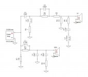
By the way, in the picture of the schematic the tweeter is inverted. That was just done for phase checking (the line with the deep null). Normally the two drivers should be connected in the same phase.
Oh, you asked about if the lack of bass would go away. Yes, as much as can be. The issue you had was your speakers had no baffle step compensation, so you were only really hearing the midrange to treble of them.
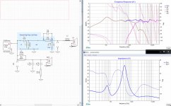
L1/R1 are the BSC (baffle step compensation) Plus L1 forms part of the low pass filter with C1 (2nd order-ish) as well.
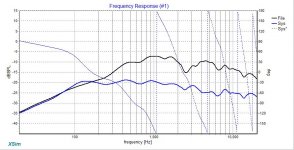
This is a much better balanced speaker than you had before. Lets compare it to the original crossover with the FR down to 20 Hz. The black line is the original curve. The blue the new one. The output is decreased as a result of the EQ added, but look at the relative output at 100 Hz. vs. 1 kHz. Now the level is only -3 dB where before it was -16 dB down. Looked at it in relative terms, we have lifted up the 100 Hz level (and below it) by around 13 dB. That's about 8x the relative output power. 🙂
Bottom line: We've pushed the -3dB point (relative to 1 kHz) from 500 Hz to around 90 Hz! 🙂
Also the response is a lot smoother overall. Sadly, there are no free lunches however. We pay for the equalization with reduced overall sensitivity.

You might be able to get a little more bass (20 - 30 Hz lower -3dB) out of the boxes if you port them. Get WinISP and try out your driver, and cabinet combination. See if you can come up with a reasonable port in the 1.5" diameter to 2" diameter range for those speakers. 🙂
Otherwise, with the cut off being what it is, it's an ideal candidate for a subwoofer. 🙂 You should submit them for THX certification say I. 🙂
Best,
Erik
L1/R1 are the BSC (baffle step compensation) Plus L1 forms part of the low pass filter with C1 (2nd order-ish) as well.
This is a much better balanced speaker than you had before. Lets compare it to the original crossover with the FR down to 20 Hz. The black line is the original curve. The blue the new one. The output is decreased as a result of the EQ added, but look at the relative output at 100 Hz. vs. 1 kHz. Now the level is only -3 dB where before it was -16 dB down. Looked at it in relative terms, we have lifted up the 100 Hz level (and below it) by around 13 dB. That's about 8x the relative output power. 🙂
Bottom line: We've pushed the -3dB point (relative to 1 kHz) from 500 Hz to around 90 Hz! 🙂
Also the response is a lot smoother overall. Sadly, there are no free lunches however. We pay for the equalization with reduced overall sensitivity.
You might be able to get a little more bass (20 - 30 Hz lower -3dB) out of the boxes if you port them. Get WinISP and try out your driver, and cabinet combination. See if you can come up with a reasonable port in the 1.5" diameter to 2" diameter range for those speakers. 🙂
Otherwise, with the cut off being what it is, it's an ideal candidate for a subwoofer. 🙂 You should submit them for THX certification say I. 🙂
Best,
Erik
Attachments
Last edited:
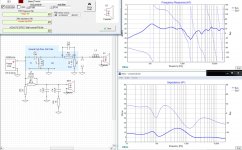
Without wanting to take anything away from the impressive work you have done on the crossover I have noticed a problem with FRD files you are using.
The frequency measurements you are using all appear to be gated far-field measurements. This means the frequency response is limited by the gate time.
In post 193 a pulse response for a woofer measurement shows a gate time of 3.229ms for the woofer. (The gate time is the time between the red and orange lines.) This means there is no useful frequency data below 1/3.339ms or about 300Hz in your FRD files for the woofer.
You really need to splice in the ungated near-field measurements to get the full picture of the frequency response.
Robert
- Status
- Not open for further replies.
- Home
- Loudspeakers
- Multi-Way
- 2 Way speakers - Suggestions on improvements?