Robot, should have been far-field, but not gated. 🙂 If it were gated as you say the woofer response would cease as you say, but it doesn't. Usually if you gate any driver the data just stops. The FRD in the crossover keep going.
Sultanen did a lot of measurements, so I suspect that post 193 and what was used for the crossover were different. 🙂
I can't swear to what Sultanen did though!
Erik
Sultanen did a lot of measurements, so I suspect that post 193 and what was used for the crossover were different. 🙂
I can't swear to what Sultanen did though!
Erik
You really need to splice in the ungated near-field measurements to get the full picture of the frequency response.
Robert
You are right of course about how gating affects the limits of the frequency response. However I disagree that the ungated near field is needed in this particular case.
As you clearly understand, splicing in the ungated near field is a compromise to get quasi-anechoic FR and phase response of the speaker below 300 Hz or so and exclude the room and surface effects. In this case it's a purely academic measurement and IMHO has little value except to prevent you from seeing the effect of the room and surface boundaries which we want in the first place. 😀
As others have pointed out, in a two way with high crossover point (which this is!) the process of measuring the woofer near field and splicing it with the gated response can be completely side stepped. We'll get the practical frequency response of the woofer+box+room and by doing so gain the ability to incorporate the room and surface boundaries effects into the crossover design so long as we use "rose-tinted glasses" while looking at the bass.
On the other hand, attempting to create an accurate crossover in the mid-bass to bass range is impossible without the quasi-anechoic response of the woofer and/or midrange. I'm not saying near-field woofer measurements are never useful but rather that understanding why it's useful allows us to avoid following the test recipe by rote.
As others and I have found, using far-field measurements exclusively for a 2-way is a pretty efficient and sometimes better method in crossover design. I invite anyone who doubts it to come to my place in San Francisco. Bring booze or food. 😀
Best,
Erik
Last edited:
Not sure if it was clear, but the very last image I posted where I compared the original vs. new crossovers the minimum f was 20 Hz, so this is why I don't think the woofer FRD was gated.
Best,
Erik
Best,
Erik
Last edited:
Hi Erik
When a gated measurement is made the sound level does not suddenly drop to zero below the 'cut off frequency'. The microphone will still register the lower frequencies but the gating means a full wavelength is not measured for these lower frequencies so the measured sound level of these frequencies will be less that it really is
If you look at post#209 from Sultanen the last two images show a gated and an ungated measurement for the woofer.
Robert
Sorry if i messed up explaining my measurement method, since i started using ARTA instead of Tombstone ALL my measurements has been gated. In ARTA the invalid frequency range is represented by the yellow line in the bottom left corner of all FR screenshots. It might have been unclear that they still was gated when i stopped posting impulse/gate screenshots like in #200.
This was why i was taking nearfield and farfield measurements(that i still think is valid but needs to be merged and i don't know how to do this correct).
As robotc noticed i did an "ungated" measurement in #209 just to show what happenes when i extend the gate and introduce room noice.
Regarding old measurements i think that we can ignore all the old once as "learning history" and only rely on #208(imp), #209(farfield), #210(nearfield).
Last edited:
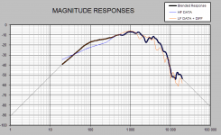
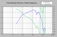
I did play around a little with the Excel sheet "FRD Response Blender 2.0".
I will post my settings(mainly default i think) and the resulting graphs and blended FRD file.
Settings:

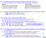
Final Blended Minimum Phase Response:

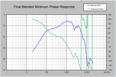
MAGNITUDE RESPONSES:

I will post my settings(mainly default i think) and the resulting graphs and blended FRD file.
Settings:
Final Blended Minimum Phase Response:
MAGNITUDE RESPONSES:
Attachments
Hi Erik
When a gated measurement is made the sound level does not suddenly drop to zero below the 'cut off frequency'. The microphone will still register the lower frequencies but the gating means a full wavelength is not measured for these lower frequencies so the measured sound level of these frequencies will be less that it really is
If you look at post#209 from Sultanen the last two images show a gated and an ungated measurement for the woofer.
Robert
Ah. In OmniMic it just shuts off like a brickwall so that's what I was basing it on.
Erik
Sultanen,
Good experience for when you do a 3-way. 😀
I was meaning to ask you. Even your blended response is pretty smooth. I was expecting big dips and valleys. Do you listen in a room with a lot of open corners that lead to other parts of the house?
Erik
Erik.
Good experience for when you do a 3-way. 😀
I was meaning to ask you. Even your blended response is pretty smooth. I was expecting big dips and valleys. Do you listen in a room with a lot of open corners that lead to other parts of the house?
Erik
Erik.
Sultanen
A couple of comments
Have you seen this paper by Jeff Bagby? It makes the blending process very clear.
Did you include the baffle step correction when you blended your nearfield measurements?
Robert
A couple of comments
Have you seen this paper by Jeff Bagby? It makes the blending process very clear.
Did you include the baffle step correction when you blended your nearfield measurements?
Robert
Sorry, misread something. 🙂
Ignore the previous content here.
Omnimic does this all for me. 😀 😀 😀
Erik
Ignore the previous content here.
Omnimic does this all for me. 😀 😀 😀
Erik
Last edited:
Sorry guys for a slow response this time, had a really busy weekend..
Okey, so i got my "woofer wall" merged frd file put together now. Redid the nearfield measurement at 0.497V just to make sure i had good data and it looked almost identical to the former lower voltage nearfield measurement so i'm pleased with that 🙂
Following the guide that robotc provided i merged "farfield wall" + nearfield + baffle step correction and got the following results:
Merging range 300-600Hz:

Full range:

With minimum phase:

FRD is attached 🙂
Okey, so i got my "woofer wall" merged frd file put together now. Redid the nearfield measurement at 0.497V just to make sure i had good data and it looked almost identical to the former lower voltage nearfield measurement so i'm pleased with that 🙂
Following the guide that robotc provided i merged "farfield wall" + nearfield + baffle step correction and got the following results:
Merging range 300-600Hz:
Full range:
With minimum phase:
FRD is attached 🙂
Attachments

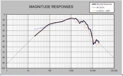
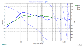
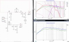
Here is eric's latest Xsim crossover design with the new woofer data 🙂
OLD FR (Green)
NEW FR with merged nearfield+baffle step correction (Blue)

I hope i did a good job with this, im quite eager to hear this crossover design soon 😀
OLD FR (Green)
NEW FR with merged nearfield+baffle step correction (Blue)
I hope i did a good job with this, im quite eager to hear this crossover design soon 😀
Attachments
Inverting the tweeter makes sense, but wait! 🙂 Ignore that for now.
With the new woofer data the BSC has over compensated. You want it to look more like the green line around 125 Hz or so. So you'll want to reduce the compensation in the woofer (coil + resistor). Then you'll need to bring the tweeter level up too. 🙂
It's a domino effect. The tweeter phase matching may fix itself when you are all done, so there's no point in attempting to optimize it just yet. The proof of good phase matching is that inverting the tweeter causes a big null. If inverting the tweeter removes a null, then that's how the speaker should be wired. 🙂
Let's discuss more of that later. 🙂
Best,
Erik
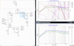
Hum, i just tried to invert the tweeter and now it aligns better, why and should i do that? 😛

Okey, lets get into inverting later 🙂Inverting the tweeter makes sense, but wait! 🙂 Ignore that for now.
With the new woofer data the BSC has over compensated. You want it to look more like the green line around 125 Hz or so. So you'll want to reduce the compensation in the woofer (coil + resistor). Then you'll need to bring the tweeter level up too. 🙂
It's a domino effect. The tweeter phase matching may fix itself when you are all done, so there's no point in attempting to optimize it just yet. The proof of good phase matching is that inverting the tweeter causes a big null. If inverting the tweeter removes a null, then that's how the speaker should be wired. 🙂
Let's discuss more of that later. 🙂
Best,
Erik
Now it looks quite nice! =)
BUT, we are not in phase so inverting the tweeter does not give us the awesome big null. How would you go about getting the phase to mach up better?
Attachments
Last edited:
Gah! Too many phase plots. 🙂
Look at just the drivers, with crossover and with the phase. you see where the line goes across the entire graph? That's when it crosses the 180 crossing point. You want that to line up for the tweeter and woofer, or as close as possible.
That FR looks really nice though, I don't think you are far off.
Good candidates to tweak are C4, R6, C1, R2 and C3. Try pushing those a little in either way to see if they improve your phase matching. But keep in mind, perfect phase alignment rearely happens as you never put your head in a vise. 🙂 90 degrees is a little further than I'd like though, 30 or less would be better.
Best,
Erik
Best,
Erik
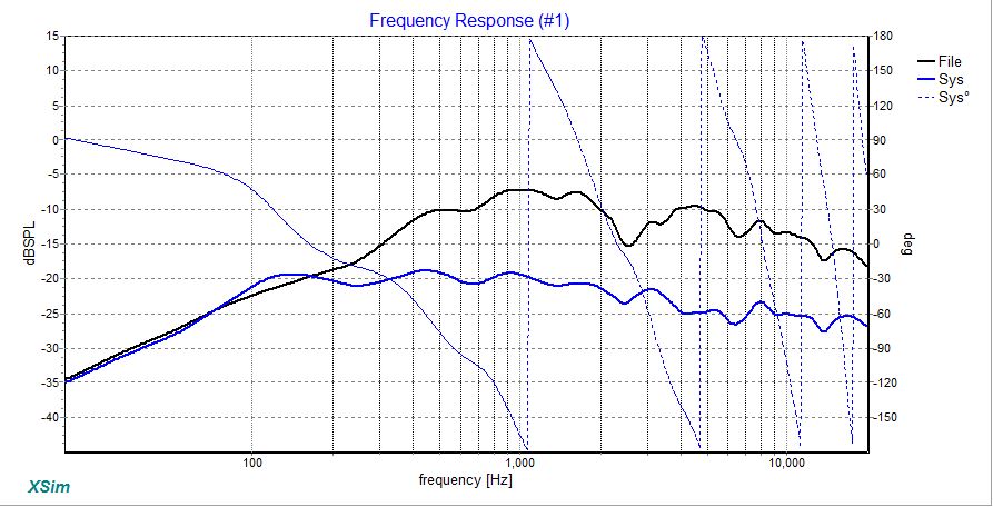
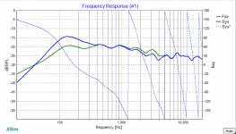
You mean the three vertical lines at about 1500Hz right? Im trying to get them closer together by playing with the components but aint getting it much closer =/ C1 is the component that affects the phase the most but when i lower that to get it to match up better the FR shoots up in the sky and i dont manage to lower it without ridiculous values on other components 😕Gah! Too many phase plots. 🙂
Look at just the drivers, with crossover and with the phase. you see where the line goes across the entire graph? That's when it crosses the 180 crossing point. You want that to line up for the tweeter and woofer, or as close as possible.
That FR looks really nice though, I don't think you are far off.
Good candidates to tweak are C4, R6, C1, R2 and C3. Try pushing those a little in either way to see if they improve your phase matching. But keep in mind, perfect phase alignment rearely happens as you never put your head in a vise. 🙂 90 degrees is a little further than I'd like though, 30 or less would be better.
Best,
Erik
Best,
Erik
attached Xsim project as a reference =)
Attachments
Last edited:
From a quick look, try to push your crossover frequency up a little, to around 2 kHz. 🙂
Also, use the L Pad circuit block instead of separate resistors. It's a lot easier to adjust the level and maintain constant impedance.
Erik
Also, use the L Pad circuit block instead of separate resistors. It's a lot easier to adjust the level and maintain constant impedance.
Erik
Thanks for the tip with the L-pad, alot better 🙂From a quick look, try to push your crossover frequency up a little, to around 2 kHz. 🙂
Also, use the L Pad circuit block instead of separate resistors. It's a lot easier to adjust the level and maintain constant impedance.
Erik
I managed to push the crossover to about 2kHz but the phase is petty much unchanged 🙄
Attachments
- Status
- Not open for further replies.
- Home
- Loudspeakers
- Multi-Way
- 2 Way speakers - Suggestions on improvements?