Which software are you using to make your measurements?
It is not a good idea to measure the tweeter from 20Hz up. You might cause some damage. The spec sheet you posted starts the impedance measurement at 200Hz.
Robert
RobotC is right, but meh, if your voltage stays very low (~ 1V) you'll be OK, especially since these are unusually rugged tweets. Starting at 200 Hz isn't bad to get a complete profile. They're a little closer to glorified full-rangers. 🙂
Hey, if you blow them it's an excuse to buy a new one..... 😀 😀
Best,
Erik
Haha, im cursed! What could be the reason for my high values? Im using a 99ohm resistor(measured by DMM) but its not a fancy high accuracy one. I still think that i should get closer to the correct values anywayHaha, no way. 🙂
Driver should be around 3-8 Ohms at the bottom. 🙂
Manufacturers usually get the impedance charts right, but little else is trustworthy. 🙂 Compare your tweeter with the spec sheet.
Best,
Erik
Im aware of this butWhich software are you using to make your measurements?
It is not a good idea to measure the tweeter from 20Hz up. You might cause some damage. The spec sheet you posted starts the impedance measurement at 200Hz.
Robert
Im aware of this but i did the measurements on the tweeter in full range with 2.90V and they survived that so i figure that this will be fine since i use much less during these measurements =)RobotC is right, but meh, if your voltage stays very low (~ 1V) you'll be OK, especially since these are unusually rugged tweets. Starting at 200 Hz isn't bad to get a complete profile. They're a little closer to glorified full-rangers. 🙂
Hey, if you blow them it's an excuse to buy a new one..... 😀 😀
Best,
Erik
I am sure it is an error in how you are measuring the impedance not the resistor value.
What method are you using?
Robert
What method are you using?
Robert
And this is why I spent the extra $49.95 or whatever to get Dayton DATS V2 with my OmniMic. 🙂 I press a button, I get graph, I import into XSim. Life is good. Women come for miles in the San Francisco Snow and Ice to hear my speakers. They say "How can you be single?" I say "I know, right?"
I will try to play around with this, i will make it eventually!I am sure it is an error in how you are measuring the impedance not the resistor value.
What method are you using?
Robert
Yea, it's easy money to spend when you finally realize that you spend like 50hours to save $50 😀And this is why I spent the extra $49.95 or whatever to get Dayton DATS V2 with my OmniMic. 🙂 I press a button, I get graph, I import into XSim. Life is good. Women come for miles in the San Francisco Snow and Ice to hear my speakers. They say "How can you be single?" I say "I know, right?"
Haha, yea, how could you? 🙄
By the way, i ordered parts for the mic amp today, will probably get them in the middle of next week =)
A quick and dirty way to measure driver Z at any frequency is to put the driver in series with a 100 ohm 2 watt (or bigger) pot, and drive that series circuit from a high feedback power amp that has a very small output Z (significantly less than an ohm), and once you get it all running with a sine wave generator driving the poweramp, adjust the pot such that there is equal volts across the pot, as compared with across the speaker driver that's in series with it. Then pull the pot out of the circuit and measure it with an ohm meter. The pot will have the same resistance as the speaker driver at that frequency. Not as quick as the Dayton or other method, but you can see that it makes sense, that it's accurate, and it costs next to nothing. If I had the Dayton jig, I'd do it this way as well (once or twice) just to check the accuracy of the Dayton jig.
Last edited:
Great for 1 data point but pita for many. If i had to do it manyally i would use a fixed resistor, measure voltage across it at each frequency. Put into a spreadsheet and you can do all the math with a cut and paste.
Each of these approaches requires an oscilloscope and signal meter though.
The scope of course is assumed to have a flat sensitivity vs. voltage, which few multimeters have.
Each of these approaches requires an oscilloscope and signal meter though.
The scope of course is assumed to have a flat sensitivity vs. voltage, which few multimeters have.
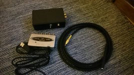
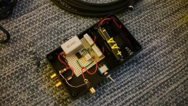
Tonight i got my WM61A mic + amp built. I think that im fairly pleased with the result and it looks surprisingly neat 😀. Have only tested that it works but will use it for measurements tomorrow 🙂
I used the VI schematics on John's page :John Conover: Using the Panasonic WM61A as a Measurement Microphone
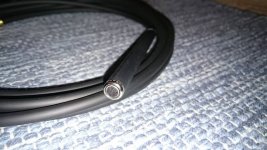
The WM61A is unmodified and attached to a 3m microphone cable.


I used the VI schematics on John's page :John Conover: Using the Panasonic WM61A as a Measurement Microphone
The WM61A is unmodified and attached to a 3m microphone cable.
Attachments
It's a little late for you, but I just added a page on measuring speaker distances you might be interested in to my blog here.
A Speaker Maker's Journey: LM-1 Testing Driver Distances
A Speaker Maker's Journey: LM-1 Testing Driver Distances
Thanks =) I hope everything works as expected to 😛 But that will have to wait until probably tomorrow, didn't have time to measure anything today. Valentines day after all ^^I like the presentation a lot! That's why I never make this stuff. 🙂
Erik
Thanks for the link, i think that i got the hang of most thats in there from your great guidance here but i will read it all and calculate my distances from the data i measure with my new shiny mic 😀It's a little late for you, but I just added a page on measuring speaker distances you might be interested in to my blog here.
A Speaker Maker's Journey: LM-1 Testing Driver Distances
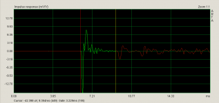
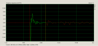
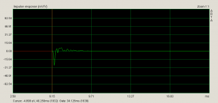
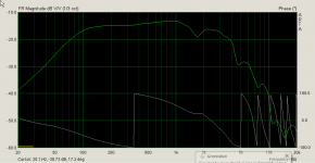
Okey, so iv'e done some new measurements with my new fancy mic+amp, here is what i got:
All measurements was made at 2,83V, tweeter was 102cm of the floor. All measurements was started at 6,125ms(both near and far field).
Far field 1m from speaker, never moved mic or speaker:
-Tweeter


-Woofer


-Tweeter+woofer


-Woofer wall - listening position


All measurements was made at 2,83V, tweeter was 102cm of the floor. All measurements was started at 6,125ms(both near and far field).
Far field 1m from speaker, never moved mic or speaker:
-Tweeter
-Woofer
-Tweeter+woofer
-Woofer wall - listening position
Attachments
-
 2016-02-15 20_42_25-Smoothed frequency response (Untitled).png34.2 KB · Views: 164
 -
 2016-02-15 20_42_09-Untitled - Arta.png16.7 KB · Views: 177
 -
 2016-02-15 20_33_17-Untitled - Arta.png18.3 KB · Views: 169
 -
 2016-02-15 20_33_45-Smoothed frequency response (Untitled).png34.5 KB · Views: 158
 -
 2016-02-15 20_45_32-Untitled - Arta.png16.7 KB · Views: 169
 -
 2016-02-15 20_45_47-Smoothed frequency response (Untitled).png32.2 KB · Views: 171
 -
 2016-02-15 21_15_33-Smoothed frequency response (Untitled).png32.2 KB · Views: 164
 -
 2016-02-15 21_14_23-Untitled - Arta.png19.9 KB · Views: 173
Near field 0.4cm from cone:
-Tweeter


-Woofer


Also attached FRD files in a ZIP here =)
-Tweeter
-Woofer
Also attached FRD files in a ZIP here =)
Attachments
-
 2016-02-15 20_59_00-Smoothed frequency response (Untitled).png33.4 KB · Views: 167
 -
 2016-02-15 20_58_45-Untitled - Arta.png16.3 KB · Views: 162
 -
 2016-02-15 21_06_33-Smoothed frequency response (Untitled).png34.3 KB · Views: 169
 -
 2016-02-15 21_06_17-Untitled - Arta.png16.6 KB · Views: 159
 -
FRD.zip56.3 KB · Views: 49

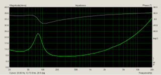
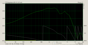
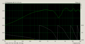
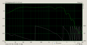
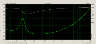
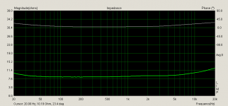
And now i did the impedance measurements with the combined resistance of the wires subtracted(line in+gnd, lineout + gnd, speaker+gnd) at 1,8ohm(yea i know thats crapy).
Tweeter

Woofer

Tweeter
Woofer
Attachments
These measurements look much better. You have done a great job with your new microphone and amp.
You haven't mentioned it but did you calibrate your soundcard?
Robert
You haven't mentioned it but did you calibrate your soundcard?
Robert
Check the impedance graphs yourself, but they look much more realistic than before. 🙂
I would do the far field measurements no further than1m though. 6ms ~= 2 meters I think. 🙂 The response curves for the individual drivers look really good.
I'm surprised you aren't getting more of a lift from the wall for the woofer though. I thought for sure placing it against the wall would improve the reponse somewhat.
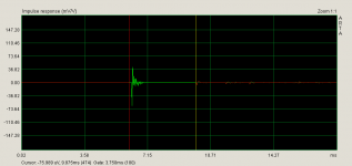
Anyway, they look great. Make sure you include phase in your impedance and fr if at all possible. Measure 3' from listening position and you should be ready to create a crossover in XSim. Er, wait, did you do driver distance already?
Best,
Erik
I would do the far field measurements no further than1m though. 6ms ~= 2 meters I think. 🙂 The response curves for the individual drivers look really good.
I'm surprised you aren't getting more of a lift from the wall for the woofer though. I thought for sure placing it against the wall would improve the reponse somewhat.
Anyway, they look great. Make sure you include phase in your impedance and fr if at all possible. Measure 3' from listening position and you should be ready to create a crossover in XSim. Er, wait, did you do driver distance already?
Best,
Erik
Last edited:
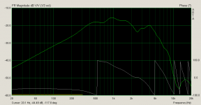
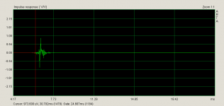
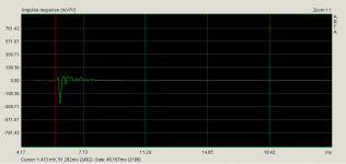
After taking a look at the near-field graphs i figure that they looked way to flat to be correct? I measured them at 2.83V as well. What i tried now was to lower the voltage to 1.41V.
Tweeter


Woofer


Tweeter
Woofer
Attachments
-
 2016-02-15 23_35_06-Untitled - Arta.png15.5 KB · Views: 160
 -
 2016-02-15 23_35_23-Smoothed frequency response (Untitled).png34.5 KB · Views: 159
 -
 2016-02-15 23_28_53-Untitled - Arta.png16.6 KB · Views: 158
 -
 2016-02-15 23_29_30-Smoothed frequency response (Untitled).png34.9 KB · Views: 155
 -
nearfield-1,44V.zip19.1 KB · Views: 41
- Status
- Not open for further replies.
- Home
- Loudspeakers
- Multi-Way
- 2 Way speakers - Suggestions on improvements?