A thanks to all the members who responded to the email send out the 6.sep2024 might be worth a while together with the 5th groupbuy?
I see my only advice in response to the email to buy another set turned into a "To top it off"-feature for future buyers... It's nice, but with all the bashing on the sidelines, this project is starting to loose that DIY appeal that had my attention to being with.
Keep is civil.
Best regards from someone who already bought V4.0 and V4.2
I have just requested the EF3-5 option instead of the -4, but I wonder about driver SOA when swinging the sorts of low Z loads that that set of outputs should handle, got plans involving a couple of bridged pairs.
Does anyone have an amplifier output device protection design for this thing yet? I tried to come up with something, but the pin header lacks some of the signals I would want, so mine is a bit messy to install.
I went for a fairly simple current limiter (About 4A per device) with the SOA enforced by a STM32 measuring Vce, current and heat sink temperature and doing sums to ensure the junctions stay safe, seemed both easier and better then trying to tune a multi slope VI limiter.
Sometimes digital really is best.

Hi all, I would build Wolverine, but my system it's all balanced.
It's possible to get balanced inputs?
It's possible to get balanced inputs?
I use @felix1024 's protect made for Wolverine, very nice. Compatible with both AC detect on LPS or psu_good pins on hypex or cobra SMPS. 12V (or 5V bypass reg)
https://www.diyaudio.com/community/...he-wolverine-build-thread.385920/post-7772925

https://www.diyaudio.com/community/...he-wolverine-build-thread.385920/post-7772925
Attachments
Hi Jeff,The protection header was meant to connect to an optoisolator that's tuned to trigger at the SOA of the outputs. I prefer digital protection too.View attachment 1446293
I have used this system in my YouTube build, it works very well however I did need to add a couple of Zener diodes to each of the optocouplers on the psu board in my build which was a great suggestion from JJS in the Wolverine team.
You can use a balanced converter in front of the amplifier. Alternatively you can just use an adaptor at the output of your preamp depending on its topology. I am currently using a balanced system also and it is working well.Hi all, I would build Wolverine, but my system it's all balanced.
It's possible to get balanced inputs?
Anything additional you add in front of the amplifier needs to have a very low noise floor.
This is a really neat option 👌I use @felix1024 's protect made for Wolverine, very nice. Compatible with both AC detect on LPS or psu_good pins on hypex or cobra SMPS. 12V (or 5V bypass reg)
https://www.diyaudio.com/community/...he-wolverine-build-thread.385920/post-7772925
View attachment 1446304
Can you show a schematic for what you are describing?Hi Jeff,
I have used this system in my YouTube build, it works very well however I did need to add a couple of Zener diodes to each of the optocouplers on the psu board in my build which was a great suggestion from JJS in the Wolverine team.
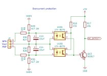
I am currently testing this circuit for overcurrent protection. The output will be coupled to a tiny processor, much like in Felix's circuit. R29 and R30 introduce a simple slope VI limiter, and Q13 increases the sensitivity of the optocoupler (with respect to a simple load resistor). I have to test this circuit yet but anyone who thinks this is a bad idea please let me know.
Attachments
Unfortunately not since I just soldered the Zeners across the optocoupler output.Can you show a schematic for what you are describing?
Happy to chat over PM about this if you need to
I tried to send you a PM but the forum says I'm not allowed to???
The optocoupler output in the schematic I posted was connected to an input on an ATMEGA328 so we're not likely talking about the same application, but I'm always curious to see other digital protection schemes.
The optocoupler output in the schematic I posted was connected to an input on an ATMEGA328 so we're not likely talking about the same application, but I'm always curious to see other digital protection schemes.
Is it possible to run this amplifier fully in class A? I know that it is designed as a Class AB amplifier and displays unbelievable low distortion figures, but all amplifiers I have built in the past always sounded better and better by raising the standing current as far as the temperature of the heatsinks allowed. It would be mandatory to lower the rail voltage then to say +/- 30V. The standing current I have in mind is between 2 and 3A. I have heatsinks that allow such dissipation.
Peter
Peter
Hi Jeff, I sent you a PM with a photo of the fixI tried to send you a PM but the forum says I'm not allowed to???
The optocoupler output in the schematic I posted was connected to an input on an ATMEGA328 so we're not likely talking about the same application, but I'm always curious to see other digital protection schemes.
- Dan
Hi Peter,Is it possible to run this amplifier fully in class A? I know that it is designed as a Class AB amplifier and displays unbelievable low distortion figures, but all amplifiers I have built in the past always sounded better and better by raising the standing current as far as the temperature of the heatsinks allowed. It would be mandatory to lower the rail voltage then to say +/- 30V. The standing current I have in mind is between 2 and 3A. I have heatsinks that allow such dissipation.
Peter
If you lower the rails you can try but you need to monitor the bias very closely. The Vbe multiplier in this amp has been very carefully setup for optimum A/B bias for best performance. Let us know how you go if you try.
- Dan
Hi Peter,
I'm just going to throw this out there. From experimental findings over a few decades on real amplifiers.
With a good amplifier, distortion reduces to a point where increasing bias does nothing except increase supply artifacts in the output. That's it. That and it runs hot as heck if you increase it too much. Class A buys you absolutely zero with a good design. Any other issues don't go away with increased bias current either.
The myth of class A only applies to amplifiers that have problems. Then why bother?
Anyone here got a diagram giving the mounting holes and connector positions, I am trying to do a board that I want to stack on top of the amplifier board down at the power and speaker terminal end, and need to make sure the mounting holes will line up (and ideally the power and speaker terminals), it also needs to be short enough to clear the driver heatsink where used. I thought this was in build documentation, but that just seems to have the UMS hole locations that are less then completely clear.
I know, I know, go and get the calipers out and take the chassis to bits again.....
If one of the design team could throw a mechanical measurement layer on kicad with the holes and board edge and just export that as a pdf and dxf, that would be wonderful, and I don't think it gives anything away.
I know, I know, go and get the calipers out and take the chassis to bits again.....
If one of the design team could throw a mechanical measurement layer on kicad with the holes and board edge and just export that as a pdf and dxf, that would be wonderful, and I don't think it gives anything away.
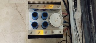
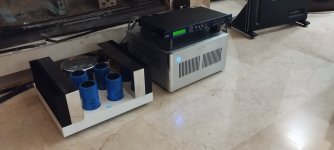
Beautiful work. I'd love to learn more about what you use to machine all of that sheet metal.
The caps with the logo are stainless steel.
The rest are aluminum, it has a different treatment with the appropriate ointments and enough rubbing,
The rest are aluminum, it has a different treatment with the appropriate ointments and enough rubbing,
- Home
- Amplifiers
- Solid State
- DIY Class A/B Amp The "Wolverine" build thread