M
To many empty words with no meaning at all
A very decisive difference,
it is by no means as marginal as you would like to portray it here.
Either you can't distinguish the fundamental connections or you simply don't want to. Perhaps it's a question of education, a misunderstanding or simply a lack of specialist knowledge and the competence to make a fundamental analysis?
I'm completely at my wit's end. I am sorry.
Unfortunately, your line-by-line description of the two fundamentally different concepts is misleading and simply not really 100% correct.
This whole number is slowly becoming a farce.
To many empty words with no meaning at all
The wise guys still arguing?
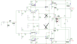
I guess this is the final #98 schematic plus a few additional changes by hbt. Changed GND, so that one may have separate GND lines from input and the rest.

Routing, second attempt. First was a disaster. I am still not proud of this - maybe I give it a new try tomorrow.

I guess this is the final #98 schematic plus a few additional changes by hbt. Changed GND, so that one may have separate GND lines from input and the rest.
Routing, second attempt. First was a disaster. I am still not proud of this - maybe I give it a new try tomorrow.

You did not like my suggestion that last time I made it.One can actually hear a very quiet 100Hz tone directly at the speaker membrane.
The only thing missing for our crystallizing A1 reboot forum project is a correctly dimensioned power supply unit.
Any suggestions?
Pick a good amplifier as a starting point and improve it. For example, a class A version of the Wolverine could add another leading zero to the THD rating. It could be the new winner of the THD wars (not that <1ppm THD matters).
Ed
PSU Suggestions (EdGr) not Wolverine
If #98 oszillate, please fix it dear Bernhard, show us the way to do it.
If #98 oszillate, please fix it dear Bernhard, show us the way to do it.
Hello M0rton,
the PCB already looks very good, but:
(maybe) turn Q13,14 by 90 degrees ..!
Thank you very much.
greetiings,
HBt.
the PCB already looks very good, but:
- Q13 & Q14 must be removed from the main heat sink, as well as Q11 & Q12
- Q13 and Q14 can be given a small but separate heat sink, which looks professional and of high quality - they won't need one, but the typical tiny one won't do any harm
- Q11 & Q12 belong to the front end, near Q1 & Q3
(maybe) turn Q13,14 by 90 degrees ..!
That's perfectly normal, three iterations are standard. So don't get angry. It's great that you're taking on the challenge - a beautiful and further KiCad project.Routing, second attempt. First was a disaster. I am still not proud of this - maybe I give it a new try tomorrow.
Thank you very much.
greetiings,
HBt.
It is redrawn by me, is it the same as yours functionally and correct?
Your schematic from this post, I redraw it, only want to know if I made any errors.
You can find my model library in the Stellema thread, as I already wrote.
Dear Bernhard,
if you indicate simulation results by name with my name abbreviation H Bt., then I would ask you to simulate my circuit exactly (with my models) - I would like it better if you left my name out.
It is already a request or even a demand that I have made several times.
"Freundliche Grüße,
H Bt."
Attachments
"One can actually hear a very quiet 100Hz tone directly at the speaker membrane." [HBt.]
This statement is nothing more than a factual confirmation of your comment @EdGr. It refers solely and exclusively to the MF-A1 model currently available for purchase.
However, you also have to stick your ear directly to the cone of the woofer.
This statement is nothing more than a factual confirmation of your comment @EdGr. It refers solely and exclusively to the MF-A1 model currently available for purchase.
However, you also have to stick your ear directly to the cone of the woofer.
Don't be confused, one might get the wrong impression - but we all know these scenes from our school days or apprenticeships.The wise guys still arguing?
Competence wrangling over the sovereignty of interpretation - childish stuff. One might assume that this phenomenon is currently booming in Germany.
Laugh, cry or ignore
greetings,
HBt.
PS
Every user has the opportunity to contact and communicate with me using the PM function.
Schematic #98 is one idea among countless!
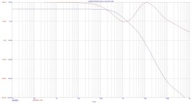
What are C10 / C13 for ?
Remove both.
If you want, reduce C3 to 47p for higher bandwith and less margins.
Compensation may be further optimized.
Somebody should cross check stability and perhaps built a quick prototype before launching a pcb.
lol
You posted a schematic and @m0rten puts time and effort into a layout.
Plot with C3 = 47pf:
Remove both.
If you want, reduce C3 to 47p for higher bandwith and less margins.
Compensation may be further optimized.
Somebody should cross check stability and perhaps built a quick prototype before launching a pcb.
Schematic #98 is one idea among countless!
lol
You posted a schematic and @m0rten puts time and effort into a layout.
Plot with C3 = 47pf:
Attachments
Quick Reminder of the original MF-A1

Dearest Bernhard,
I know right from the start what you're getting at and what cards you're trying to play.
This bone has been gnawed away.
M0rton knows that this idea still has to pass the practical test - and it definitely will.
Incidentally, the effective limiter is still missing! Wouldn't you like to invest your energy in this direction?
Unfortunately I'm busy for the rest of today, but feel free to send me a PM.
Bye for today,
HBt.
You can find my model library in the Stellema thread, as I already wrote.
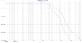
Where is your definitive schematic ? Where is your stability plot ?
I use the schematic from post #202.
Updating to -16 and C transistors + dual output filters doesn't change anything.
Schematic with 2 x 100pF removed, input 47pF, standard transistors, single output filter
Remark: Once again coupling caps in the signal path...
Remark: Once again coupling caps in the signal path...
Attachments
Last edited:
Could you let me know why? Religiously?Better without
OK.No, simulation
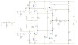
You are shooting in the dark. C88 in #214 could work if the Zero it creates cancels out a Pole in your circuit. A1 is a relatively simple 2 stage amplifier. It only has 2 major Poles. In this case, make one of Pole more prominently so that you know where it is.
Try this.
PS: I strongly suggest to swap out 3055, and replace it with something like 2sc5200. Low ft 3055 is your largest obstacle to compensate.
Last edited:
PS: I strongly suggest to swap out 3055, and replace it with something like 2sc5200. Low ft 3055 is your largest obstacle to compensate.
I only fixed compensation here, everything else = don't care.
#219 still bad in simulation.
Please address further suggestions @hbtaudio 🙂
- Home
- Amplifiers
- Solid State
- An A1 descendant - a relentless analysis