="wahab, post: 7845943, member: 117480"]
This has already been explained, a transimpedance stage has high output Z while a EF has low output Z, in the case
of the MFA1 that s even worse as the 2N3055/MJ2955 has to provide both a current gain and a voltage gain
and doing both at the same time will yield very poor linearity, indeed using the VAS as final stage is a very
bad idea.
With a total of 4 transistors in the chain that make about 10^8 current gain, a blameless has 10^10 current gain,
whatever the way this gain will be used, either as voltage ampification or as current amplification.
I love your rhetorical questions. Answer: but yes, darling.
So...
@wahab tried to point out that
1) the vas output is inferior.
2) the total theoretical gain of a 5 transistor amp is much higher than that of a 4 transistor amp.
-->Again, in a practical implementation, you can get a higher open loop gain from that 5 transistors.
--> Once again, the distortion reduction is better in the 5 transistor amp.
Now why did you try to proove him wrong with your calculation of a closed loop ?
Trolling ?
There are said to be people who recognize a signal path regardless of the system in place.
I would like to explain this briefly.
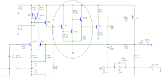
Like these people, our signal, the sound to be amplified, follows a very specific path, straight ahead, from location A to location B. On this path, our hiker comes across signs with a drinks bar for refreshments, Q10, Q8, Q17, Q18, Q7 and Q6, he counts six signs.
n+1
He will always count one more signpost on his way, which this hiker guarantees.
One more! It's always better than one too few, or so these experts would like us to believe.
bye, bye ...
HBt.
PS
For practical purposes, we consider our walker's route to be constant, regardless of the number of bars and clues.
I would like to explain this briefly.
Like these people, our signal, the sound to be amplified, follows a very specific path, straight ahead, from location A to location B. On this path, our hiker comes across signs with a drinks bar for refreshments, Q10, Q8, Q17, Q18, Q7 and Q6, he counts six signs.
n+1
He will always count one more signpost on his way, which this hiker guarantees.
One more! It's always better than one too few, or so these experts would like us to believe.
bye, bye ...
HBt.
PS
For practical purposes, we consider our walker's route to be constant, regardless of the number of bars and clues.
Attachments

Many of the later posts have been deleted.
Provocative and argumentative squabbles between members will not be tolerated.
Provocative and argumentative squabbles between members will not be tolerated.
From experience I can attest to some of the problems that can arise using the scheme used by the A1. Long ago (early 1980's) I had a slightly-similar idea but implemented it using complementary Szilaki-pair outputs, configured as a matched buffered-pair stage. It always oscillated, no matter what I tried. I thought that the SZ pairs were fighting each other and dropped the approach. All the things I tried that DID tame the oscillation also mangled the overall frequency response. Designs like this appear to be tricky.....certainly, beyond my skills at the time. It would be interesting to re-visit that using LTSpice.
An approach like the JLH auto-bias scheme has a fundamental advantage, in that the idle current in the output stage is controlled by a separate feedback loop that has a very low-frequency cutoff. It is separate from the audio-signal feedback path. This could offer a different set of opportunities w/regard to improving an A1-like design, if one wants to pursue it. It won't work very well with anything but a class-A amplifier but that's where the A1 resides anyway. I understand there are purists that abhor capacitors in the signal path: but, in fact, the bias-control loop(s) really are NOT in the main signal path.
Yes, the auto-bias scheme does have some problems. The most apparent is the necessity of trimming the + and - output currents so the output offset is acceptably low. But that can be done using a servo, something that wasn't very common back when Hood originally published his designs.
Something I've been curious about is what the transient voltage(s) that appear on the collectors of the transistors that drive the output Q's look like. I had an amplifier design that used a similar approach, used to reduce the voltage drop across and power dissipation of the drive transistors. The amp exhibited some really odd problems with fast-rising signal edges and I (eventually) found large transient voltages on the drive transistors' collectors. AC-grounding the collectors eliminated those transients and cleaned up the output waveforms as well. Hindsight says it likely was the transistors' Miller capacitance screwing up the main signal path. At the time I was just happy to find a way to fix the problem.
In the case of the A1, the source impedance feeding the drive transistors is pretty low so this may well be a non-issue.
It would be interesting to see what simulations have to say about this.
In the case of the A1, the source impedance feeding the drive transistors is pretty low so this may well be a non-issue.
It would be interesting to see what simulations have to say about this.
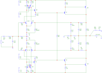
See the appendix for the final version 1.2, this is a possible reboot of the MF-A1 whitout any distortions.
The further and final iterations can be found here:
Ein neuer Anfang
The further and final iterations can be found here:
Ein neuer Anfang
Attachments
- Home
- Amplifiers
- Solid State
- An A1 descendant - a relentless analysis