I didnt suggest to use a CFP with gain, quite the contrary, in fact i was talking of the advancement of the topology,The third way
View attachment 1379992
Just as "wahab" suggested through the flower - pulling together and counter-coupling locally; old hat, known as CFP. It works perfectly in operating classes B, AB and especially A.
In no time at all we end up with the Elektor LFA Class A 50Wpeak Amplifier ... but the A1 20Wpeak approach is sufficient for us.
Then it's your turn to play your card, I'm looking forward to your hand.
😎
HBt.
this MFA1 from 1988 is in some way less advanced than the 1972 Goodmans 90.
Also adressing the IPS without looking at the flawed OS is like pumping more air in the front wheels while the back
ones are rolling on the rims.

I understood exactly what you wanted.I didnt suggest to use a CFP with gain, quite the contrary, in fact i was talking of the advancement of the topology,
By the way, there is no amplification, G = 1 ---> 0dB.
Please explain this in detail, because it's not true!this MFA1 from 1988 is in some way less advanced than the 1972 Goodmans 90.
This comparison is also nonsense, but it sounds very nice and reads concisely.Also adressing the IPS without looking at the flawed OS is like pumping more air in the front wheels while the back
ones are rolling on the rims.
kindly,
HBt.
This comparison is also nonsense, but it sounds very nice and reads concisely.
-------------------------------------------------------------------------------------------------------------------------------------------
Keep original topology, add vertical feature (mirror) to increase olg, conceal the errors of the inferior ops to a certain extend.
=
Also adressing the IPS without looking at the flawed OS is like pumping more air in the front wheels while the back
ones are rolling on the rims.
Dear Bernhard,It very looks like all attempts to improve the original schematic will lead to a standard design.
I can't agree with you. An improvement to an existing concept consistently forgoes a change in the concept and therefore also a fundamentally different topology.
You want to go for the three-level division with power. This perfectly encapsulates the voltage amplifier (the second stage), it is completely shielded from the input (the differential point) and the output (the emitter-follower). Not 100%, of course.
Of course, you can now play your very last trump card, the current-mirror in the collector circle of the differential amplifier. However, this is anything but an A1 that has been improved in detail, i.e. modified; it is a familiar power amplifier.
I assume that we are not talking at cross purposes, but that you know exactly why it is only a matter of comparing systems (concepts, topologies).
Perhaps you want to disguise it with the word “methods”?
Detailed improvements are not a gender change.
An MF-A1 (whose creator is said to be "Tim de Paravicini") must also remain an A1, the structure of the holding skeleton must remain unchanged.
Appodictically, one could also make other demands, according to which my extreme proposal (posting #98) would no longer be valid.
HBt.
Oh Bernhard,-------------------------------------------------------------------------------------------------------------------------------------------
=
what is such a contribution supposed to mean ???
#
At this level, we should immediately stop the (hopeless) communication (between the North and the South).
You don't seem to be interested in any kind of rapprochement. That is regrettable.
what is such a contribution supposed to mean ???
To separate quote 1 from quotes 2 and 3
An MF-A1 (whose creator is said to be "Tim de Paravicini") must also remain an A1, the structure of the holding skeleton must remain unchanged.
Your opinon
Maybe the grandmaster's goal was not to create the ultimate fidelity amplifier but one that sounds nice, to attract a certain audience.
Good,
then wait and support "M0rton's KICad" work from now on. So that a beautiful, universal PCB can be created for the community.
then wait and support "M0rton's KICad" work from now on. So that a beautiful, universal PCB can be created for the community.
Last edited:
Is this supposed to be an endless loop, a chat?Your opinon
Bye,
HBt.
logout
Is this supposed to be an endless loop, a chat?
This is a discussion forum.
People are free to express their ideas, thoughts and opinions.
FYI 🙂
"Wie recht Du damit hast!" How right you are!This is a discussion forum.
People are free to express their ideas, thoughts and opinions.
FYI 🙂
And now back to the facts, to the technology, to the design of audio power amplifiers.
"Ebenfalls zu Deiner Information,"
fyi
HBt.
99.99% of amplifiers use followers as ops, there seems to be an advantage in doing that.
Most bipolar followers even have additional preceding buffer stages --> EF2, EF3 to load the vas as little as possible.
Hint: Low current gain of power transistors. 🙂
If your goal is to drive low impedance speakers with high fidelity from a collector... nobody hinders you.
I wish you success.
Most bipolar followers even have additional preceding buffer stages --> EF2, EF3 to load the vas as little as possible.
Hint: Low current gain of power transistors. 🙂
If your goal is to drive low impedance speakers with high fidelity from a collector... nobody hinders you.
I wish you success.
Binsenweisheiten - Truisms
but my wish is a different one - which you can read repeatedly from all my contributions.
Please,
back to the topic - "Zen Mod's Modification" or "HBt.'s suggestion", a forum iteration called reboot.
Alternatively, you can also suggest your final circuit proposal. However, it would be nice if the original A1 concept remains recognizable; i.e. no three-stage blameless concept, not even double symmetrical.
HBt.
correct99.99% of amplifiers use followers as ops, there seems to be an advantage in doing that.
Most bipolar followers even have additional preceding buffer stages --> EF2, EF3 to load the vas as little as possible.
also correctHint: Low current gain of power transistors. 🙂
Thank you very much,If your goal is to drive low impedance speakers with high fidelity from a collector... nobody hinders you.
I wish you success.
but my wish is a different one - which you can read repeatedly from all my contributions.
Please,
back to the topic - "Zen Mod's Modification" or "HBt.'s suggestion", a forum iteration called reboot.
Alternatively, you can also suggest your final circuit proposal. However, it would be nice if the original A1 concept remains recognizable; i.e. no three-stage blameless concept, not even double symmetrical.
HBt.
One chance to improve the original ops could be to substitute the power transistors with multiple parallel BD139 / 140.
8 x 8W = 64W
Maybe.
8 x 8W = 64W
Maybe.
Dear Bernhard,
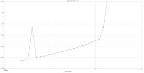
and now I regret to inform you that MC12 certifies that my suggestion has an even slightly better THD than your last throw.
I am very sorry, you have lost the competition by a very narrow margin.
Bye,
HBt.
and now I regret to inform you that MC12 certifies that my suggestion has an even slightly better THD than your last throw.
I am very sorry, you have lost the competition by a very narrow margin.
Bye,
HBt.
I realize that,
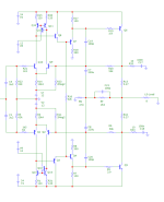
so I'm attaching the circuit again - you can check it yourself. The models are known or can be found in the “Stellema thread”.
You might also like to try out the extension from posting #153.
Good luck with it.
#
I'll wait and put my money on “M0rton”.
so I'm attaching the circuit again - you can check it yourself. The models are known or can be found in the “Stellema thread”.
You might also like to try out the extension from posting #153.
Good luck with it.
#
I'll wait and put my money on “M0rton”.
Attachments
No, I have been busy... But tomorrow I will start routing - and you clever guys can come up with a better compromise. Let's race! 😎@m0rten
Don't be put off, the version "0", i.e. posting #98, will be retained. Have you already had the time and inclination to start the routing?
greetings,
HBt.
I believe this is the best one, A1 with current mirror, and MOSFET.
The opamp is required to get DC fixed. The amp itself has no idea where the output DC level is. Without the opamp, It would blow up your speakers easily.

With about 200ma bias, -75dB 10K THD into 8 Ohm at 25W.

The opamp is required to get DC fixed. The amp itself has no idea where the output DC level is. Without the opamp, It would blow up your speakers easily.
With about 200ma bias, -75dB 10K THD into 8 Ohm at 25W.
- Home
- Amplifiers
- Solid State
- An A1 descendant - a relentless analysis