I upload it here, bcause i dont know if in PM is possible....
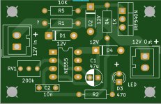
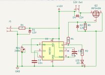
The time delay has one resistor R1 and D1 as a zener diode. If you use 12 volts it is not needed and you must short R1 with a bridge. Because the NE555 can deliver 200 mA, i put a Mosfet for more power to the output. Simple little circuit...
The Stereo version of the P30ZF was made by Hicoco. I haven't test, but i think it will work.
The P30ZF Gerber is not shown right on PCBWay, there is often an error. With Altium or JLCPCB it works...
The Board has one missing value for one BC560 at the input
Peter
Attachments

How is the fault finding Chris?next step:
check transistors
check regulators.
Diodes ok...all resistors okay.
Strange is that all 10 pcs. of 78N15A JRC regulator do not show 15V at the output pin without load! -->14,3V
with 10mA load i got 12,6V
these are from mouser -company Nisshinbo?!
recheck this in my office..because i never se this like that!
Strange is that all 10 pcs. of 78N15A JRC regulator do not show 15V at the output pin without load! -->14,3V
with 10mA load i got 12,6V
these are from mouser -company Nisshinbo?!
recheck this in my office..because i never se this like that!
Hi Peter
yes i tested it with 5mA, 10mA, 27mA with different resistors. i did this with my equipment at home.
i was really wondering. 2pcs. 7815 were in the PCB, the other 8pcs. were original from the bag from mouser but the same result- really strange.
2nd test is in my "office" (school for EE practice) - exactly the same result...
 🙄
🙄
yes i tested it with 5mA, 10mA, 27mA with different resistors. i did this with my equipment at home.
i was really wondering. 2pcs. 7815 were in the PCB, the other 8pcs. were original from the bag from mouser but the same result- really strange.
2nd test is in my "office" (school for EE practice) - exactly the same result...
🙄i checked my notes before i put into operation. without op amp i checked voltage at PIN 4/8 it was 29.88V. so ti was fine
aaaaarghh.. somthing is strange here...today i recheck the regulators again...
because i do not believe that...
aaaaarghh.. somthing is strange here...today i recheck the regulators again...
because i do not believe that...
so test finished.
regulators are working but. according to the datasheet between 14,4V to 15,6V.
mine have about 14,725V
i do not expect that the input cap was needed. i use mostly STM or other products and for short test input cap was never needed.
So with 10µF it is working fine. still 14,722Volt.
so regulators 7815 are okay with 22V input and 31mA output current.
next step tomorrow..
chris
Hi
from 10 pcs i got just 4 with 14,73V wih a load of 31mA.
other are about 14,62 V
still in the big tolerance of JRC 78M15A --> 14,4V - 15,6V
from 10 pcs i got just 4 with 14,73V wih a load of 31mA.
other are about 14,62 V
still in the big tolerance of JRC 78M15A --> 14,4V - 15,6V
Please STOXX, check the vias of GND with DMM - should be good contact.
because at the dartzeel amp (NHB-108) they have troubles with the PCB... mine was good.
because at the dartzeel amp (NHB-108) they have troubles with the PCB... mine was good.
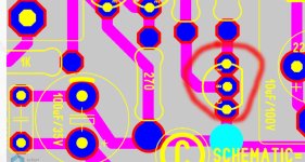
Hmmm, did they think that hole in the middle of the board was on the ground plane?Please STOXX, check the vias of GND with DMM - should be good contact.
because at the dartzeel amp (NHB-108) they have troubles with the PCB
Is is not connected to anything but it looks like the center point or star of ground connection.
Perhaps this oddity tricked other users?
The board is nice. Ground is good. Yes it has a non-connected hole in the middle of star ground, which is not a star ground.
Yes that is a bit odd.🤔
Attachments
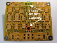
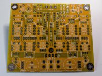
At the first look i also thougt about a starground, but the hole really has no connection. Don't know what is it good for... 
I hope i find the time in the next days to try more opamps too. If i dont find the reason of the white noise the project will die.
Peter
I hope i find the time in the next days to try more opamps too. If i dont find the reason of the white noise the project will die.
Peter
Hmmm, did they think that hole in the middle of the board was on the ground plane?
Is is not connected to anything but it looks like the center point or star of ground connection.
Perhaps this oddity tricked other users?
The board is nice. Ground is good. Yes it has a non-connected hole in the middle of star ground, which is not a star ground.
Yes that is a bit odd.🤔
Hi stoxx
yes the middle looks like that but it is "just" a mounting hole...me too.
chris
Hi
All transistors soldered out and checked...1pcs 559C PNP and 4pcs BC550C NPN were tested with DCA Pro. and i got from 4x testing 2 time not a transistor and they show not hfe from about 570-600...just 510hfe all 5 pcs... so out. transistor were in the front end of the amp.
i started at the other side...but... 😉
negative regulator are all okay and from onsemi. from 10 pcs i have got 4x 15,266V and 6 pcs. with 15,168V. so my first measurement on the socket of the op amp with 29.88V was okay --> V+....14,75 + V- .....15,26
kr
chris
post 362 is not correct.I use BC550 and BC557. try to get the hfe group araound 400-500hfe. match as good as you can.
BC559C, BC550C (about 580hfe)
Hi
step by step i re-build the pre amp.
now checking the PSU. i use my lab PSU with 22V input for the regulators each rail. current limit is per rail 30mA.
i measure the consumption of the complete amp.
chris
step by step i re-build the pre amp.
now checking the PSU. i use my lab PSU with 22V input for the regulators each rail. current limit is per rail 30mA.
i measure the consumption of the complete amp.
- regulators are working fine (V+ 14,7x and V- 15,2xV).....okay
- no transistors. no op amp. -led is okay about 13,5mA consumption (regulators and LED, +7,65mA, -5,82mA)...yellow LED is not really bright....okay
- so for calculating the consumption of the op amp with 15V you have to subtract about 7,5mA from V+ and about 5,8mA from V-
- no transistors. but in op amp NE5532 current on each rail now. total consumption -rail 15,75mA, +rail 13,97mA
op amp 49720 -rail 17,24mA, +rail 15,41mA
op amp 4562 -rail 18,92mA, +rail 17,04mA....okay - next step tomorrow...each transistor line after another...
chris
Last edited:
- Home
- Amplifiers
- Solid State
- Clon C-3850