As i wrote before... i had hum too with the C3550 preamp, but it was my mistake. Something was not soldered right because of my changes of some components. Very rare mistake, thinking of the lead free solder....
Don't know what the reason of the hum in your preamp. I think its a faulty capacitor. Faulty from the beginning. That may be the cause for a higher current too, to blow the fuse. Unbalanced current in the secondary windings...just a guess. I don't think it is a small capacitor, must be one of the big ones after the diodebridge....
Perhaps you can see something on the lid of the capacitor ? A minor change ?
Peter

pre amp hum:
as i wrote yesterday i just check the fuses and i was wondering that the prim. fuse with 315mA is blown. both sec. rail fuses with 100mA were okay. it is not nice to know that the primary fuse was blown...therefore...
in my lab i checked again the signal in and out with fg and scope...nothing special.
i go to my room for listening. switch on everything and sound was playing. after a short dinner a was back and the sound was fine. no hum.
after an hour i realized between switching of some titles that i got a hum...wtf...thats loud...!!!!
i checked all connectors - nothing. after this time i always get an increasing hum after turn on the pre amp.
today morning i checked again with shorted inputs. so the DAC does not make troubles...fine..
other power cable or RCA connectors doesnt help.
hum is at starting very low but increasing after 20-30 seconds to loud!!
i will check again...today afternoon and will report back. maybe my power amp get with the pop a damage?! (FX8 ) hopefully not...
chris
Sounds like you damaged the input to the opamp and/or the front end is wired wrong.hum is at starting very low but increasing after 20-30 seconds to loud!!
Or your power supply has an error in it or how it is connected to the circuit.
sorry stoxx...but i did not change the wire...or change anything with connection....during testing....but yes. it is something wrong.
As i wrote...the day before yesterday 4 hours without problem....what ever...i have to check
good new my FX8 is working fine...phuu...power amp is working!
kr
chris
As i wrote...the day before yesterday 4 hours without problem....what ever...i have to check
good new my FX8 is working fine...phuu...power amp is working!
kr
chris
i probe around the pre amp...searching...
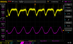
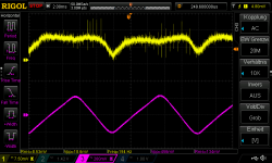
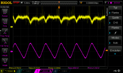
input shorted...to much ripple. 50Hz is visible.
RCA with DC coupling you see about 10mV DC offset...with DMM i measure about 6,6mV each RCA.
pop on and off is huge if you think you have about 1,5Vpp into a power amp!
connection earth show with LCR Meter (DCR) 0,08 ohms.. so no problem.
RCA checked no bad connector --> no contact to housing -earth
input shorted...to much ripple. 50Hz is visible.
RCA with DC coupling you see about 10mV DC offset...with DMM i measure about 6,6mV each RCA.
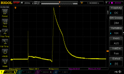
pop on and off is huge if you think you have about 1,5Vpp into a power amp!
connection earth show with LCR Meter (DCR) 0,08 ohms.. so no problem.
RCA checked no bad connector --> no contact to housing -earth
Attachments
-
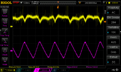 7815_ripple at input_432mVpp.png23.2 KB · Views: 53
 -
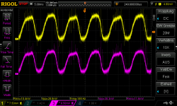 RCA_input_yellow left_R pink_DC coupled.png29.3 KB · Views: 65
 -
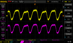 RCA_input_yellow left_R pink_AC coupled.png27.4 KB · Views: 51
 -
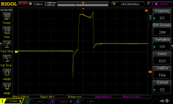 pop on_1,66Vpp.png12.7 KB · Views: 49
 -
 pop on _1,95Vpp.png14.4 KB · Views: 53
 -
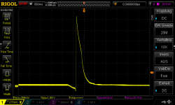 pop off_1,89Vpp.png14.3 KB · Views: 47
 -
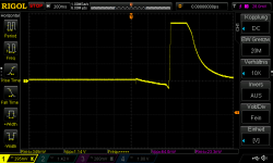 pop off_1,14Vpp.png13.3 KB · Views: 52
 -
 7915_ripple at out_288mVpp.png22.8 KB · Views: 50
 -
 7915_ripple at input_456mVpp.png18.9 KB · Views: 49
 -
 7815_ripple at ouput_400mVpp.png22.6 KB · Views: 52
I am wondering about that "time delay". RCA is ok, you changed the opamp ...🙁
I would search for a bad transistor or capacitor.... the rail voltages are ok and nearly the same ? No faulty diodebridge ?
Peter
I would search for a bad transistor or capacitor.... the rail voltages are ok and nearly the same ? No faulty diodebridge ?
Peter
Did you couple those 2 transistors close together? Maybe temperature drift.
You match transistors firston Ube them on Hfe.
You match transistors firston Ube them on Hfe.
thanks Peter and MRhifitunes that you try to help. 😉
but step by step...i am sure now that some transistors must be damaged. Why? --->
i start from the transformer to the regulator:
Voltage on both rails without the amp pcb = 17,25VAC both windings...okay
but
if i measure the current which is drawn that i was very surprised! -when the board is switch on it starts with about 94mA to nearly 101mA !!!
both rails (+V, -V). i use a slow blow fuse therefore the fuse is still healthy.
....not okay!
then i but out the regulator:
both rails draw a current about 48mA...
+V rail starts with 48mA...go down to 43,2mA
-V rail starts with 47,6mA and do not change
...not okay
caps before and after the regulator are okay. measured with DMM and LCR Meter
is use 1000µF 50V / and after the regulator 180µF (too big?)...all 4 caps are okay...no short cut or optical damage....okay
KBP304G rectifier diode is okay
next step:
check transistors
check regulators.
kr
chris
I do not think that a capacitor with 180 µf is too big. The question is if its necessary and making something better as the original 100 µf. 100 nf at its pads is the better solution and more important.
Peter
Peter
Hi Peter
it is that what i have in my box. (10nF film cap is soldered parallel)
what me really wonder is that without regulator i draw 45mA, why...and where?
the regulator should be the "connection between rectifier and the the amp part.
chris
it is that what i have in my box. (10nF film cap is soldered parallel)
what me really wonder is that without regulator i draw 45mA, why...and where?
the regulator should be the "connection between rectifier and the the amp part.
chris
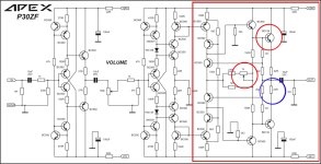
I would solder out the transistors next to the opa and measure them. Dont think the problem is near to the output. The two face to face transistors on each side of the board need the first look. If you have soldered in some capacitors more in the opa area get them out to test if the problem remains...
As you wrote...step by step... stupid work, i know. But what else to do ?
Do you remember my searching for two days to find the cause why one FH9 was not working right....after that time i found it....6,8k instead of 680 ohm....😎
Good luck...i am sure you will find the reason for the disfunction...
As you wrote...step by step... stupid work, i know. But what else to do ?
Do you remember my searching for two days to find the cause why one FH9 was not working right....after that time i found it....6,8k instead of 680 ohm....😎
Good luck...i am sure you will find the reason for the disfunction...
Last edited:
Chris, you are temping fate with this risky turn on/off sequence.i think i did yesterday a stupid thing.
after switching off the pre amp i heard a loud pop. then i made the mistake and switched again on - the same - POP!
okay now i realized that the on/off pop is loud...****...then i switched off without power amp.
Power amp should always be turned on LAST and turned off FIRST.
You can potentially damage the downstream amplifier and speakers from preamp on/off transient voltage.
For a little bit more safety...
Time delay Relais...anti pop/plopp
🙂
Time delay Relais...anti pop/plopp
🙂
Attachments

Last edited:
What is a P302F preamplifier?For a little bit more safety...
Time delay Relais...anti pop/plopp
Attachments
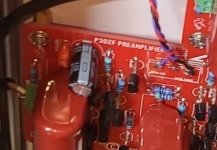
Hi STOXX,
you can read about https://www.diyaudio.com/community/...delity-amplifier.164093/page-659#post-6341301
Years ago Apex was so kind to give a few schematcs to the comunity. The schematic of the P30ZF was one of them....
I can upload the gerber files. Mono or/and stereo
you can read about https://www.diyaudio.com/community/...delity-amplifier.164093/page-659#post-6341301
Years ago Apex was so kind to give a few schematcs to the comunity. The schematic of the P30ZF was one of them....
I can upload the gerber files. Mono or/and stereo
Is this the schematic you worked with?The schematic of the P30ZF was one of them....
Attachments
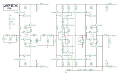
Very similar, but i the P30ZF has smaller capacitors in. There are 10 uF build in and only three...The input is different and other components.
I dont know why there are two different versions, don't know about the meanining of "ZF".
I found the P30ZF on youtube first, not here in the forum. About the existing of another version (P30) i had read later, but had the P30Zf ready build....
The threads are a chaos, as Chris wrote. Nothing is realy splitted to themes...
Peter
Attachments
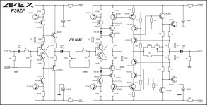
The output section is more like a power amplifier. It could be a capable headphone amplifier with minor changes. The partial negative feedback loop was removed. The ZF can drive much smaller loads over longer distances. The trim pot allows you to adjust the bias so you could go for more class A operation. I like the ZF version. Zero OpAmp is not a bad thing either.Very similar,
So yeah, please send me the Gerbers for the red boards you built in your preamp. Send me whatever you have, please. I'm also interested in your mute/delay circuit you hooked up there.
Cheers!
Attachments
- Home
- Amplifiers
- Solid State
- Clon C-3850