Do you have the final build schematic? This version is not the functional final. The bias adjust circuit as presented is virtually shorted and non-functional.The Board has...
Peter
Attachments
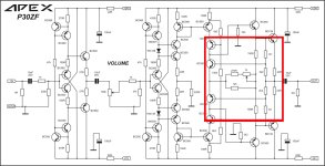
I am sorry, i have only this schematic. Others and i too asked for the function of the pot, as it is virtually shorted. I have adjusted to 500 ohm and let it in....but it is no adjustment possible on the board. Never became an anwer...
Post 13193, https://www.diyaudio.com/community/threads/100w-ultimate-fidelity-amplifier.164093/page-660, Hico changed some resistors...i had forgotten.
The schematic he used is the same.
The preamp sounds good, without adjusting the pot...
Perhaps Apex, Mr Miles, can give the answer..
Peter
Post 13193, https://www.diyaudio.com/community/threads/100w-ultimate-fidelity-amplifier.164093/page-660, Hico changed some resistors...i had forgotten.
The schematic he used is the same.
The preamp sounds good, without adjusting the pot...
Perhaps Apex, Mr Miles, can give the answer..
Peter
Hi
i had COVID and I am on the way its getting normal.
i rebuild my pre amp step by step.
i have a strange signals on the right channel:
input with 1k 1Vrms signal on both channels
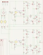
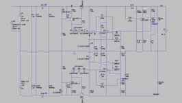
i just but in the opamp 5532 and solder the first line of the first Transistors Q2,Q7, Q9,Q5 (see schematic attached)
the scope point is on the collector of Q2 and Q9.
other transistors after that are not soldered.
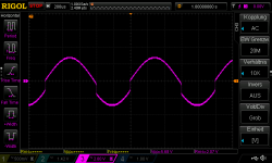
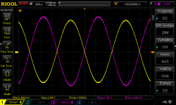
every thing looks good (pic 3, 4)
next is the bad signal....
when the next line of transistors are soldered in --> Q3,Q4, Q11, Q10
i have got a bad signal on the same scope point of Q9 and Q2 collector. pic 1
pic 2 you see the signal e.g. on the collector of Q4
so i have problems if Q2 and Q9 are under "load"
what does this "distortion" mean?
i try to change the transistors Q3,Q4,Q10,Q11 again but it is the same..????
the signal after the op amp is okay, the diff. pair Q5 qnd Q7 give me a fine signal on all pins.
chris
i had COVID and I am on the way its getting normal.
i rebuild my pre amp step by step.
i have a strange signals on the right channel:
input with 1k 1Vrms signal on both channels
i just but in the opamp 5532 and solder the first line of the first Transistors Q2,Q7, Q9,Q5 (see schematic attached)
the scope point is on the collector of Q2 and Q9.
other transistors after that are not soldered.
every thing looks good (pic 3, 4)
next is the bad signal....
when the next line of transistors are soldered in --> Q3,Q4, Q11, Q10
i have got a bad signal on the same scope point of Q9 and Q2 collector. pic 1
pic 2 you see the signal e.g. on the collector of Q4
so i have problems if Q2 and Q9 are under "load"
what does this "distortion" mean?
i try to change the transistors Q3,Q4,Q10,Q11 again but it is the same..????
the signal after the op amp is okay, the diff. pair Q5 qnd Q7 give me a fine signal on all pins.
chris
Attachments


Hi ChalkyWith the input shorted what's the dc voltage at the collectors of Q2 and Q9?
Q9 11;2 V. Q2-11;2V
LT Sim without transistors shows 11.9V
Good Channel with Q15,16,17,18
Q14 9,7V. Q13 -9,7V
About 16 years ago , member Jwilhelm built it , too. Powered it with my super-reg (below).Have you ever build the pitchfork line stage in real ? Not many parts. I can make a pcb for it...interesting
All on one PCB. I did not have headphones , ran some of my amps with it.
Never tested it with any distortion software , output stage should just reflect the op-amp THD.
Long time ago , I think we used OPAxxx - no issues.
Edit - I'm older wiser now . I would load the op-amp with 1K to ground.
Also , now ... I would also just use an enhanced 317/337 with shunts (denoiser).
OS
Attachments
Last edited:
Nop.. sorryHi Chalky
Q9 11;2 V. Q2-11;2V
LT Sim without transistors shows 11.9V
Good Channel with Q15,16,17,18
Q14 9,7V. Q13 -9,7V
Good channel is the same voltages.
Q14 is 11,2
Q13 is 11,7
https://www.diyaudio.com/community/...-retrofit-upgrade-any-317-based-v-reg.331491/
Turns the 337/317 into a super-reg. 100db PSRR + few nV noise without a lot of shunting. virtual ground + noise fed back through ".ADJ"
"Poor mans super-reg" I use it to power my toppings (DAC's). Perfect for line stages/ headphone amps.
OS
Turns the 337/317 into a super-reg. 100db PSRR + few nV noise without a lot of shunting. virtual ground + noise fed back through ".ADJ"
"Poor mans super-reg" I use it to power my toppings (DAC's). Perfect for line stages/ headphone amps.
OS
Looooooong thread. Sort of like my Slewmaster - CFA vs. VFA "rumble" thread (epic 10K posts). Every amp on the planet .... he he.
That's the thread these China boyz should read , like a bible. They would all design Topping and benchmark amps.
"rumble" is top 3 DIYA views/posts , up with blowtorch even.
OS
That's the thread these China boyz should read , like a bible. They would all design Topping and benchmark amps.
"rumble" is top 3 DIYA views/posts , up with blowtorch even.
OS
Apex is alright , "blame" is struggling ????
We are "badger" , Wolverine ... you can have 3K$ amps for 3-400$.
I fail to see why some pursue "dead ends" where some china boyz scam "bombed out" stupid internet
designs and even try to pass these off as any sort of SOTA ??
Spew there cheap crap boards , and then they come to DIYA and ask our help.
Create threads to have us make fun of sub standard designs.
OS
oh yes Peter...at post 289 😉
I would not want to intrude upon the headphone section. many of my PPM AB 200w amps could be easily portedpitchfork pre amp...nice...do it in a separate thread please.
to sub PPM class a headphone amps . I'd only have to power 50-300 ohm loads ? cool ! 4 ohms is sooooo hard.
OS
I recall messing around with it in LT SPICE. Quite versatile....build this. 1/10th PPM - class A - 20khz - 5V p-p - >100R load .
I used a OPA - 2604 , nearly immeasurable.
OS
Is there a board or Gerbers out there?
Cheers.
- Home
- Amplifiers
- Solid State
- Clon C-3850