
Oh , yeah ....
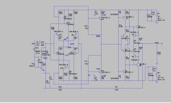
I put the "leach front end" on the OP stage - magic 1PPM BJT headphone amp !
It might need a output zobel / inductor ?? Not sure with headphones ?
As a line stage I just lightly loaded the outputs.
OS
I put the "leach front end" on the OP stage - magic 1PPM BJT headphone amp !
It might need a output zobel / inductor ?? Not sure with headphones ?
As a line stage I just lightly loaded the outputs.
OS
Attachments
Hi
if you are a fan of OPA2134 (UA-Soic8)..at reichelt it is cheap now..
reichelt -OPA2134UA (SOIC8)
if you are a fan of OPA2134 (UA-Soic8)..at reichelt it is cheap now..
reichelt -OPA2134UA (SOIC8)
Short message with success.
R Channel is working. 🙂
to be serious, i was ill and partly not concentrate, so maybe i did some mistakes.
What i learned too is that the BC559C CDIL should be checked several times...some parts were broken, out of the box. i checked with DCA75 pro several times and sometimes i gut " 2PNP junction diode"....crap..
chris
Every part I stuff into a PCB is measured first. I'll go so far as to match 1% resistors in certain positions.some parts were broken, out of the box
Transistors and J-FETS? Well, let me tell you, each and everyone is tested, sorted and matched.
I used to play the 'good enough random game' when I was younger but I learned many years ago, that approach is a major fault in itself.
A random undefined approach yields random results. Not what I'm going for on a build.
Glad you found some light on your journey.
Hi Stoxx.
yeap...that is the best way.
i did so. no piece soldered in before tested.
but it is month ago. strange..
chris
yeap...that is the best way.
i did so. no piece soldered in before tested.
but it is month ago. strange..
chris
my pcb is partly done...mouser delivered faster.🙂
gain is set with 680R --> 4.61dB
i need:
transistors - have BC557/BC550 - BC337/327 - decision not done.
transformer 30VA 2x15V
47k resistor
and time😉
ooops...i see...i was too fast...some resistors are not good soldered...have to check...
hi did you ever 're-clon' the C3850 using the bc337/327 ?? if yes, what were your results ?
regards
gaz
Hi gaz
no i haven´t build another version...sorry.
Actually i am doing nothing. i am active in the house of my daughter before winter is coming.
...so for audio is not really time. maybe in 2 weeks.
chris
no i haven´t build another version...sorry.
Actually i am doing nothing. i am active in the house of my daughter before winter is coming.
...so for audio is not really time. maybe in 2 weeks.
chris
hi Chris, thank you for the reply, and dont apologize 'life happens' 🙂 there is always something that needs to be done !!
i also am interested in the 337/327's because they are cheap and high current handling. i found a document regarding the 337's, its not a white paper, it's the results of experiments/tests that a Czechoslovakian guy did, he says that the 337's are capable of very low input noise.
maybe the c3850 circuit could be run at higher current to give better results using the 337's ! i would try this for my self but i am currently trying to relocate away from europe.
https://d1.amobbs.com/bbs_upload782111/files_14/ourdev_440418.pdf
gaz
Here's mine! Saw the youtube video a few months ago and ordered two kits! Finally built it up this last weekend.
At first it seemed the general consensus was to increase the resistors connected to pins 1 and 7 to lower the gain, but now it seems like lowering it to 22ohms is recommended?
I used 470 or 560 (can't remember) and socketed them for easy tweaking in the future. I think the pre-amp sounds excellent. Before this I was using the B1 pre amp with the NuTube, and before that some JISBOS. I'm very happy with this Pre, as its noise free (B1 can had tube microphonics) and seems very clear. I used all the kit components except for the 100n caps near the opamp were canged out to WIMA.
Hi...
if you had made no change after taken the picture i think you use a 510 ohm resistor. My idea too to change to a higher value. I am wondering why all other clones are quiet...exept mine...🙁
greets
Peter
if you had made no change after taken the picture i think you use a 510 ohm resistor. My idea too to change to a higher value. I am wondering why all other clones are quiet...exept mine...🙁
greets
Peter
Is this good for me? I am looking for a little preamp that can take my DACs 2v fixed line output and send into my poweramp. My DAC uses a passive potentiometer, and since I often have it at "9-12", I guess with dubious pot quality, I would like to build a little preamp.
My Poweramp: Input Impedance: 51 K Ohms. Sensitivity: 0.777 Volt RMS input produces 16 Volts RMS output (equivalent to 64 Watts into 4 Ohms)
My Poweramp: Input Impedance: 51 K Ohms. Sensitivity: 0.777 Volt RMS input produces 16 Volts RMS output (equivalent to 64 Watts into 4 Ohms)
Hi
you can set your needed gain as you want. you can change the resistor.
for me a gain of 2-5 is fine for a preamp.
100R is original

kr
chris
you can set your needed gain as you want. you can change the resistor.
for me a gain of 2-5 is fine for a preamp.
100R is original
kr
chris
Last edited:
I may have a funny question, so please forgive me. What is the input impedance of the basic version of this preamplifier (KIT Ali), because I was wondering if there would be a chance to connect the DAC TDA1541 output directly to the input of this preamplifier. Thank you in advance.
The TDA1541 is a current output DAC, so there would need to be some form of I/V conversion. If connected directly, the 47k load resistor on the front end would then serve as the I/V resistor, but the value is much too high for good fidelity, due to clipping. Also, it will generate DC voltage at the input. For passive I/V conversion, the I/V resistor should be less than 100R. The lower the better. Then an input DC blocking capacitor (0.5 uF PP film). I would use the preamp at full gain (100R feedback resistor in the table above), and reduce the value of the I/V resistor as much as possible, while still achieving line level voltage output.
Last edited:
- Home
- Amplifiers
- Solid State
- Clon C-3850