NTC play two roles here.
Their cold resistance slows down the charge through the caps, their hot resistance together with the caps reduces ripple and noise.
You won't find chokes that can do this.
The other factor is of course size. Chokes worth using need to be let's say 2mH at least, and they are big, and expensive.
Use this LC calculator:
https://leleivre.com/rf_resonance.html
and this RC calculator:
https://sengpielaudio.com/calculator-RCpad.htm
to find out what values achieve what.
I thought about that, but there's still an ntc on the power input board. Mostly curious to see if anyone has tried, since I've seen it mentioned, but no examples.Their cold resistance slows down the charge through the caps,
I made mine, it works, thanks for the design, the kit, the support with questions! Gonna do some A/B this weekend and try to get to know it.
I'm interested in getting a custom vinyl transfer sticker for the front of the case that says PassDIY F5m. Is that cool, or is that protected territory? Is there art blessed for this purpose for either logo, or is it up to me to find a free font that catches the vibe?
Some blue painters tape and a sharpie is good, but I thought I might try to match this fancy ALU case a little better...
PassDIY F5M should be fine AdamThorne.
Go ahead with sharing some of your ideas. 🙂
Go ahead with sharing some of your ideas. 🙂
What about the sound quality affected by NTC or resistor or choke? I heard that some people with another amp not F5m even remove resistors between caps because without that it sounds "better" for them.NTC play two roles here.
Their cold resistance slows down the charge through the caps, their hot resistance together with the caps reduces ripple and noise.
You won't find chokes that can do this.
Haha,
You'll have to explore that one yourself.
Only your ears can tell you what sounds good or not so good.
I personally don't worry about the sound of resistors, chokes, jumpers, wire.
JFETs, MOSFETs, bipolar transistors, ICs, tubes, that's a whole different story.
You'll have to explore that one yourself.
Only your ears can tell you what sounds good or not so good.
I personally don't worry about the sound of resistors, chokes, jumpers, wire.
JFETs, MOSFETs, bipolar transistors, ICs, tubes, that's a whole different story.
I dunno about all that, honestly I'm pretty skeptical about sound quality vs parts that the signal doesn't even go through, and on top of that, "big" sound quality claims are generally not supplied with much objective evidence at all, so.What about the sound quality affected by NTC or resistor or choke?
My interest in using a choke in this instance is pretty much just power supply stiffening and overkill. I've already considered water cooling it, too.
I used 4 of these in my Aleph J. It’s the quietest amp I’ve ever built bar none.
https://www.mouser.com/ProductDetail/546-159ZJ
https://www.mouser.com/ProductDetail/546-159ZJ
I've done similar on several builds using one power supply and a pair of chokes per channel after the PS smoothing caps. Adds a bit of isolation and dead quiet. Probably helps more in my situation where the basic power supply is in a separate box with an umbilical to the amp with the chokes (and another pair of caps before the amp circuitry).
This is a good thread for you to go over:
https://www.diyaudio.com/community/threads/clc-vs-crc.337738/
I have personally always done CRC. However, I have been on the fence a few times thinking I would give CLC a shot. Well, after reading the thread above, I haven't really settled on a decision but I do at least feel more educated on the topic.
The Hammond 159ZJ seems to be a go to for CLC
Looking at the F5m PS board, I don't see why CLC cannot be implemented.
You could do it I guess, and just add the same CL-60 input circuit as other First Watt clones use. or the store's time delay to do that task. If I was going to use CLC I would likely use a regular linear supply like the standard First Watt clones use, and sub in the coils.I thought about that, but there's still an ntc on the power input board. Mostly curious to see if anyone has tried, since I've seen it mentioned, but no examples.
So the power supply schematic is drawn kind of funny but it is pretty much a standard CRC power supply with the R subbed with a thermistor. I had to look at the schematic for a second as it is folded around a bit. The only big difference being the 4 caps before the thermistors and two after the thermistors whereas the DIYstore universal one is equal capacitance before and after the thermistor. It may be fun to play with PSUD and see what the differences are with those two arrangements.
I like the F5m power supply for the plain fact that the V+ and V- taps are on the sides close to the amp boards. Makes for tidy wiring. 🙂
I agree with the 2xCL60 idea. You should be able to sub SL22's in place of the CL60's in the soft start. Both the CL60 and SL22 are 5 amp 10 ohm thermistors. The SL22's are a bit beefier though.
Beefy is good. We have noticed that CHEAP has it appeal among DIYers, so it's a balance...
😎
😎


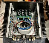
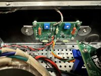
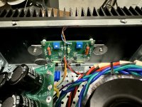
 I was wondering about the power supply voltage when setting the bias. I ended up using the 200VA because the 300vVA being out of stock at the time. When setting the bias, I notice the supply dropped to around 21v. Is that expected from the 200va? I set the bias to around .5v and it sounds great. I will attach some photos of it being stuffed in the Mini Dissipante 3U chassis
You can measure the secondary voltage. It should be somewhere around what the power supply is rated at if it is not sagging. I assume 18vac. Looking at the bias current, you should definitely be below 200 watts.
Next, you can look a the DC coming off of the rectifiers. You should see something in the neighborhood of around 24-26vdc. If the voltage going out of the power supply to the amp boards drops quite a bit, then you know your drop is somewhere in there.
If the voltage drop is on both polarities, then you probably do not have a bad solder joint. You can check the voltage drop across the thermistors and see if it is there.
Also, calculate the bias current.
For good measure, you can check the Line going into the soft start and after to make sure the drop is not there either but I suspect it is somewhere else.
glancing at the pics, it looks like a nice clean build. I don't see anything obvious poking out other than typically you would want the transformer at the front of the amp in order to cut down on noise.
I used the 200va Antek in my build, and I recall 21-22Vdc on the rails when bias was set. Unloaded, it was ca. 24V.
- Home
- Amplifiers
- Pass Labs
- F5m kit