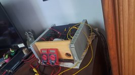
Found a 15 X 6 X 1.25 inch pair of sinks. My heat paranoia has dropped several degrees....
I just wrapped up this budget build of the F5m. A few years ago, I built the chassis and shoved a little Aleph Mini into it. I then shipped it off to TX as a gift to my dad where he used it for a few years. Well, the F5m kit is so cheap that I convinced him to ship it back so I could upgrade it! While the Aleph Mini was a wonderful amp, this F5m is certainly a step up! Tomorrow I am regretfully sending it back...
It is pretty much built as per the kit the only difference being 10,000uF caps that replaced the 4,700uF caps in the power supply. I also put snubbers on the rectifiers...
An interesting bit of information. The outputs seem to be matched quads. I didn't measure the 140/9140 mosfets but I ordered two aditional essentual kits. There are shiny IR 9140's and matt finish IR 9140's. The ones in my test board amp (in a previous post) had the shiny parts. From the two kits I ordered after the test board build, one set was shiny parts and one matt. I want to try a balanced amp so I made sure to swap out the shiny parts from the populated boards off the test amp that were destined for the Aleph to F5m project. I did not touch the trim pots. The bias and DC offset measured the same on both channels after swapping the parts.
So the goal (I am sure you will be able to tell) was not to go outside of my parts bin or what I had in my garage... So it is made out of wood, there are mismatched screws. Not to mention, UPS damaged the amp on it's way to me in CO.
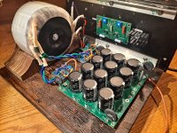
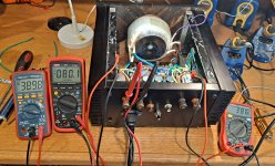
Attached are pics of the amp. The one with the ~0.380vdc drop across the source resistor was after swapping the output mosfets and not making any adjustments. DC offset was 0.080vdc on both sides as well. I of coarse adjusted them to around 0.550vdc and DC offset to ~0.0vdc...
A Video Demo'ing them so you can get a taste 🙂
Attachments
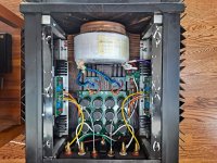
View attachment 1344224View attachment 1344226View attachment 1344227I was wondering about the power supply voltage when setting the bias. I ended up using the 200VA because the 300vVA being out of stock at the time. When setting the bias, I notice the supply dropped to around 21v. Is that expected from the 200va? I set the bias to around .5v and it sounds great. I will attach some photos of it being stuffed in the Mini Dissipante 3U chassis
hello sorry i'm a newbie can explain what is this because it's not in the kit and it's my first build
Sounding great Mike, what speakers are those?A Video Demo'ing them so you can get a taste 🙂
Pierrick59, that looks to be a soft start. There is a thermistor that is on the line in which then leads to the reds (one side of each primary). Neutral is connected directly to black (other side of primaries). the little green board that came with your kit does the same thing.
manniraj, They are the Bordeaux by Speaker Design Works. I have had a lot of speakers come and go but nothing has been able to kick these off of their pedestal so far... I built them about 5 years ago and I am very happy with them. I am also very happy with the F5m. I cannot say enough good things about that little amp.
manniraj, They are the Bordeaux by Speaker Design Works. I have had a lot of speakers come and go but nothing has been able to kick these off of their pedestal so far... I built them about 5 years ago and I am very happy with them. I am also very happy with the F5m. I cannot say enough good things about that little amp.
Mikerodrig27 i have ordered my kit a long time ago when it have been lunched there was not the small board in it at this period
does someone can telle wich parts i have to order to make the same things?
does someone can telle wich parts i have to order to make the same things?
That is just a terminal strip where you connect AC (120 or 240VAC) on one side (after the power switch), through the NTC, to the other side that goes to the primary of the transformer.
No need for a special PCB.
One can also incorporate fuses, parallel X rated caps, and so on right there.
No need for a special PCB.
One can also incorporate fuses, parallel X rated caps, and so on right there.
That green thermistor was an undocumented freebie included in the early kits, so look in your unused parts. There where no instructions for it and it does not appear in the schematics, but the photos given by 6L6 early on show how he used it, as explained by Mikerodrig and Stanislav above.Mikerodrig27 i have ordered my kit a long time ago when it have been lunched there was not the small board in it at this period
does someone can telle wich parts i have to order to make the same things?
There is also a safety cap in that photo, across the AC line-neutral, the little blue one. That was not included in the kit. Perhaps you meant that one.
Edit: see posts 806-808 in this thread for more info, pics.
Edit: see posts 806-808 in this thread for more info, pics.
Last edited:
@Pierrick59 : Members Stanislav and northpaw have already given you a lot of info. I'll just add a couple of points:
What you saw is for the AC input to the transformer and basically implements the section circled in blue in the following from the F5m article:

A commonly used part for the thermistor TH is CL60. Other 10R NTC thermistors already mentioned should work just as well.
The cap MUST be safety rated (since it's connected across AC lines). Commonly used values in FirstWatt type builds are 2200pF to 4700pF. Here's an example that should work
https://eu.mouser.com/ProductDetail/Vishay-BC-Components/AY1332M57Y5UC63L0?qs=l7cgNqFNU1iaumQu9PQ69Q==
What you saw is for the AC input to the transformer and basically implements the section circled in blue in the following from the F5m article:
A commonly used part for the thermistor TH is CL60. Other 10R NTC thermistors already mentioned should work just as well.
The cap MUST be safety rated (since it's connected across AC lines). Commonly used values in FirstWatt type builds are 2200pF to 4700pF. Here's an example that should work
https://eu.mouser.com/ProductDetail/Vishay-BC-Components/AY1332M57Y5UC63L0?qs=l7cgNqFNU1iaumQu9PQ69Q==
My bad on saying those two parts are not on the schematic; it is the parts list that they were not on. Thanks for straightening things out, Denis.
can you confirm me these parts are good to make the soft start and security like on the picture post before:
https://www.digikey.fr/fr/products/detail/amphenol-advanced-sensors/CL-60/19756
https://www.digikey.fr/fr/products/...loric-bc-components/AY1332M57Y5UC63L0/9836518
https://www.digikey.fr/fr/products/detail/amphenol-advanced-sensors/CL-60/19756
https://www.digikey.fr/fr/products/...loric-bc-components/AY1332M57Y5UC63L0/9836518
Those should work. That is the CL60 I use for FW amps. The capacitor is X1 and Y1 rated and should be good for this application.
Do you think it would be possible to install 4 x F5m channels in a Modushop case 4U/400?
So a 4 channel amplifier?
So a 4 channel amplifier?
- Home
- Amplifiers
- Pass Labs
- F5m kit


