The little black coax I use in basically everything is Mogami W2330. I absolutely love it, just bought 200’.
Umbilical should be something with 3+ conductors and a shield, such as Mogami W2799 and W2893.
Of course, in the meantime you can find an old CAT5 or CAT6 cable and use pairs from it. Might not ever need to change from that.
Umbilical should be something with 3+ conductors and a shield, such as Mogami W2799 and W2893.
Of course, in the meantime you can find an old CAT5 or CAT6 cable and use pairs from it. Might not ever need to change from that.

I thought about adding either a pair of antiparallel power diodes or a thermistor between power ground and earth ground in my UDP3. I measured a potential difference of about 15mV between the two when the UDP3 received power through an isolation transformer with it's secondaries' center tap grounded through a water pipe. In system with a floating ground but the grounds connected in the rest of my system through a Tripp-Lite power conditioner, I used alligator clips to connect the earth and circuit ground in the UDP3 together using the antiparallel diodes. I didn't hear a difference in the shot noise (whoosh sound) pt dimmer hum (angry bee) that my Pearl3 produces at max volume with the antiparallel diodes in place. I didn't test a thermistor. I've chosen to leave power ground in the UDP3 floating relative to earth ground, for now.A couple questions about the PSU.
If using the UDP3, should a Ground Loop Breaker of some sort be added? I know @rhthatcher’s board has one built in.
Also, might be a dumb question, but could the VRDN be used to power a P3? I have a board set up to be used with a Wall Wart and 18Volts. Curious if it could be used in the same chassis since a transformer isn’t used. Just a thought.
Thanks.
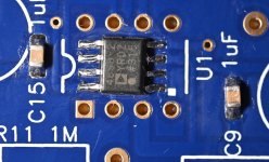
I got the smd solder work finished on both PCB's. It requires some concentration.
As you can see I won't do opamp rolling.
Looking at the images I could see I needed some "dust off" from the cotton stick from the flux removal and also some solder "dots" between the legs. That has been done after the images was taken. Now I just hope the opamps works!
It will take a while before that can be verified.
Attachments
My Pearl 3 kit arrived today (Silkeborg - Denmark).
I plan on building with 2SK170BL and 2SC2240BL in the first stage.
I don't know if the Toshiba BJTs are wasted here, but why not try them?
I plan on building with 2SK170BL and 2SC2240BL in the first stage.
I don't know if the Toshiba BJTs are wasted here, but why not try them?
2SC2240BL instead of the ZTX?
In my case I have 851 for both (there are 851 and 457 in the kit if I remember correct).
The 851 should be quite unique for its low noise so I wonder if 2SC240 can do better?
In my case I have 851 for both (there are 851 and 457 in the kit if I remember correct).
The 851 should be quite unique for its low noise so I wonder if 2SC240 can do better?
Hello All,
What is the story about capacitor C8?
The BOM calls it out as 220uf.
The circuit schematic shows a range of 100 - 1000uf.
If I recall there is mention in the thread about C8 being part of a low frequency filter to prevent pumping the woofer.
Has experience helped narrow this down, the soldering iron is hot?
Thanks DT
Yes, what I was wondering is what people have found to be best. Just being a little lazy, though I did a little googling when first I saw the chart. With proper cartridge weight/compliance the resonace frequency should be somewhere around 8-10 Hz, but memory is most subsonic filters are below that.
Just a warning. Don't drop them 🙂
Thanks for the warning, too bad it came too late! I had a couple smd capacitors that decided to take flying lessons and I haven't seen them since!
I was not planning on installing balanced outputs so all good.
Feeling relieved to have the smd caps and sk209's installed. They were a challenge for me!
What I'm struggling with is why even have a choice? If the point of the subsonic is to limit a feedback loop with your arm dancing to a different tune, first and foremost a well matched arm/cartridge and potentially isolation, and if using the subsonic why wouldn't you just set it to 15 Hz? This is above the resonant frequency of any reasonable arm/cart and well below the bass extension of LPs.
Perhaps 220uF was included in the kit for a reason...
Anyway, the point of that capacitor isn't to be a subsonic filter, it's to make sure the gain at DC is unity. A neat bonus is that it CAN be used as subsonic if you need it, with no downside to the circuit's performance.
Anyway, the point of that capacitor isn't to be a subsonic filter, it's to make sure the gain at DC is unity. A neat bonus is that it CAN be used as subsonic if you need it, with no downside to the circuit's performance.
DT & T4B, What does the build doc say about C8?
See post #1 for the doc.
The document says it is up to the builder.
Is everyone on different pages about rumble filters?
People please your thoughts.
DT
Perhaps 220uF was included in the kit for a reason...
Anyway, the point of that capacitor isn't to be a subsonic filter, it's to make sure the gain at DC is unity. A neat bonus is that it CAN be used as subsonic if you need it, with no downside to the circuit's performance.
This is a different view than is presented in the build document.
What effect does C8 have on gain at DC, as in how does it work?
Will there be an gain issue if C8 is 100uf or 1000uf as shown in the circuit schematic?
Be careful here since it doesn't look like the Toshiba NPN is pin-compatible with ZTX851.2SC2240BL in the first stage
That helps calm my poor brain, I think it was stuck in a feedback loop LOL! It still seems odd to have values below the 3.2 Hz, which in and of itself seems too low to help, perhaps @wayne might shed some additional light? In any event, it sounds like nothing to obsess over.it CAN be used as subsonic if you need it, with no downside to the circuit's performance.
Hello smndao,
I wouldn't exchange the ZETEX ZTX851 (NPN). It is still one of the lowest noise BJTs available! Together with the ZTX853 (NPN).
The PNP - 'brother' Zetex 951 is also super lownoise.
You can read about this excellent transistors in Horowitz / Hill, 'the Art of Electronics', 3rd edition, page 507 under B. Choosing a low noise BJT... Or read the complete chapter 8...? 🤔
Don't misunderstand me - the TOSHIBA 2SC2240 are really good devices.
And: each 10 Ohm - resistor in this circuit makes more noise than the ZTX851...
Cheers
Dirk 🙂
C1,C12,C8 are the reason each builders pearl will sound different. 100uf is ok for C8. There are various combos you could try out if C12 is a harsh film type, a lossy electroytic for C8 will take out C12s bite. We are assuming C1,C12 are Mundorf and C8 is from the good known audio electrolytics Muse etc. If these are not available and C1 ,C12 are Wimas, then C8 should be an electrolytic that can counter balance them. Lots of capacitor rolling fun here.Hello All,
What is the story about capacitor C8?
The BOM calls it out as 220uf.
The circuit schematic shows a range of 100 - 1000uf.
If I recall there is mention in the thread about C8 being part of a low frequency filter to prevent pumping the woofer.
Has experience helped narrow this down, the soldering iron is hot?
Thanks DT
Dont worry if you cant hear any difference. Sometimes during burn in, both the brain and components burn in 😉
The bigger C8 is the higher voltage it will charge to during rest necessitating discharge on start up, you can use dual diode strings across it if you use 1000uf
- Home
- Amplifiers
- Pass Labs
- Pearl 3 Burning Amp 2023