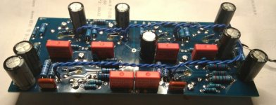
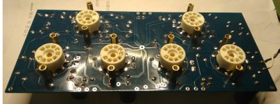
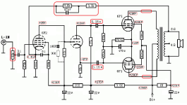
That was a result. Your own tube sockets look a whole order of magnitude better than the very rough and ready looking ones supplied. I would have thought twice about using them with the ease of replacing valuable tubes.
The dent was a bit irksome - you need a quick ding with a dolly to sort that out!
The dent was a bit irksome - you need a quick ding with a dolly to sort that out!
yes, now I just have to see how I can reduce the heating voltage, which is probably a little too high due to the 220v transformer.
I have measured 233v in the electricity grid.
2x 6P2 450 +/- 50mA, 4x 6P1 500 +/- 50mA, this means that the 2x 3.15V 3A winding is almost loaded to the limit 😱
I have measured 233v in the electricity grid.
2x 6P2 450 +/- 50mA, 4x 6P1 500 +/- 50mA, this means that the 2x 3.15V 3A winding is almost loaded to the limit 😱
I've now measured it exactly, with a load of 2 Ω resistance flow 3.1A, the heating voltage is 6.6V, 0.3V more is too much for the tubes, right? Is it enough to work with a series resistance or is that not such a good solution?
A bucking transformer should do the trick.
A simple 12v transformer inserted on the primary of the power transformer.
https://sound-au.com/articles/buck-xfmr.htm

A simple 12v transformer inserted on the primary of the power transformer.
https://sound-au.com/articles/buck-xfmr.htm
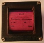
I also measured the impedance of the OPT using this method:
https://www.jogis-roehrenbude.de/Transformator.htm
(measuring method described at the end of the page)
I get almost 10 kΩ !
I compared it with my good old German EL84 PP OPT (weight 2kg)
with the China transformers (weight 1kg) and that's exactly right!

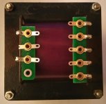
https://www.jogis-roehrenbude.de/Transformator.htm
(measuring method described at the end of the page)
I get almost 10 kΩ !
I compared it with my good old German EL84 PP OPT (weight 2kg)
with the China transformers (weight 1kg) and that's exactly right!


Seems like there must be endless versions of this thing for sale, in varying quality of parts and packing.
Guess I lucked out with mine? Was packed well, and most parts quality seemed ok, other than the weird electrolytics. I tossed and used Nichicon replacements instead. I used the supplied white box film caps. RCAs are kind of cruddy, but work for now. May replace in the future.
Main issue was the secondary wiring was reversed on my output transformers, I was able to resolve with the generous help of members here.
To reduce heater voltage, I added a pair of 1/8 ohm 7W wirewound resistors to the filament leads, this brought it down to 6.0 when fed from my wall supply of 122 volts. I ran my filament leads on the socket side of the board. Figured that might help keep AC away from any signal paths.
Currently driving my Polk Monitor 7's. Didn't think these were super efficient, but it easily drives them to a level that would probably annoy the neighbors.
Added a pilot jewel, running from the heater supply. The stainless chassis is hard, I'd recommend using a new, metal-specific bit for any drilling.
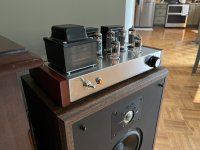
I'm really impressed with the sound quality! Fat controlled bass, luscious midrange, silky treble. Amp has dead silent background at all times; no hum or hiss.
My first tube amp experience, and everything is really holographic. The atmosphere on well done recordings like the Blue Note RVG releases is incredible. Though any well-recorded source sounds delightful.
Guess I lucked out with mine? Was packed well, and most parts quality seemed ok, other than the weird electrolytics. I tossed and used Nichicon replacements instead. I used the supplied white box film caps. RCAs are kind of cruddy, but work for now. May replace in the future.
Main issue was the secondary wiring was reversed on my output transformers, I was able to resolve with the generous help of members here.
To reduce heater voltage, I added a pair of 1/8 ohm 7W wirewound resistors to the filament leads, this brought it down to 6.0 when fed from my wall supply of 122 volts. I ran my filament leads on the socket side of the board. Figured that might help keep AC away from any signal paths.
Currently driving my Polk Monitor 7's. Didn't think these were super efficient, but it easily drives them to a level that would probably annoy the neighbors.
Added a pilot jewel, running from the heater supply. The stainless chassis is hard, I'd recommend using a new, metal-specific bit for any drilling.

I'm really impressed with the sound quality! Fat controlled bass, luscious midrange, silky treble. Amp has dead silent background at all times; no hum or hiss.
My first tube amp experience, and everything is really holographic. The atmosphere on well done recordings like the Blue Note RVG releases is incredible. Though any well-recorded source sounds delightful.
hi, have you measured how many volt the high voltage is higher than stated in the circuit diagram in the first post?
Hi, I spent my week having a cold (Covid to be precise) away from work, with some extra time on my hands.
I built this little amp, which arrived well-packaged, bought from the eBay seller "Nobsound". This was a much more rough experience than expected, albeit a learning one. In between "Google Lens" translation of the Chinese writing on the transformers and the schematic and this forum thread, I thought I had it figured out. Alas, not so fast.
What comes out of my right speaker (the left one seems dead now) is pretty awful -- music, distorted.
It seems to be sensitive to the setting of the volume knob.
I connected "Lin/Rin" to the RCA Input, "Lan/Ran" to Lin/Rin on the board, and Land to ground RCA for both and to the provided ground terminal on the board. The potentiometer produces 100 to 200 kOhm, in the expected direction. The video shows how volume, and distortion, seem to be worse when it's turned low, and the volume knob seems to turn the volume down, not up! Should "Land" not be on ground?
My input voltage is a little high, as others have noted -- 260V as opposed to be 230V (as expected, as mains is about 123V here, not 110V as per spec). I'm getting about 360V DC as input to the board.
I replaced the 75Ohm resistor on the input side with a 100Ohm resistor (because I blew it up). I would think that should only help the voltage trouble.
What could this be?
Can you post the schematic?
I have no faith in anything from China.
I bought a 10w EL34 SE ready built amp which sounded bad unless the volume was very low.
I measured it with REW and found it could only produce about 2w at reasonable distortion.
I changed some components and achieved 10w at 1.2% distortion and a vast improvement in sound quality.
https://www.diyaudio.com/community/threads/chinese-el34-6sn7gt-se-unusual-topology.401911/
So I would not be surprised if you don't have to rework it and start by measuring the voltages and anode currents so you can compare the working with the non working. The tubes probabaly need to be changed to. (Mine came with PSvanes which are supposedly not too bad)
It is oscillating , maybe a simple mistake in wiring ...
And , as was said before , use equal resistors at phase splitter cathodyne , not 27K and 30K . This is a weird chinese "invention"
And , as was said before , use equal resistors at phase splitter cathodyne , not 27K and 30K . This is a weird chinese "invention"
Last edited:
I live exactly on the other side of the channel, so it predicts the weather 🙄
Same schematic as before in this thread, same kit. Here's what I have (with translations).
I'm new to this... one thing I don't understand is: we seem to have a left and a right channel side on the board, with 2 6P1 tubes for each (push+pull, I'm guessing). The schematic just shows a single channel. However, how are the two total 6F2 tubes mapped to the channels? The schematic shows the left-in pathway, but I don't understand what's happening here...


I'm new to this... one thing I don't understand is: we seem to have a left and a right channel side on the board, with 2 6P1 tubes for each (push+pull, I'm guessing). The schematic just shows a single channel. However, how are the two total 6F2 tubes mapped to the channels? The schematic shows the left-in pathway, but I don't understand what's happening here...
@batteryman ... I posed the schematic. Given that others have built this amplifier with success before, and commented on it sounding good, I would think it should be possible to make it work.
@Depanatoru ... OK. Maybe I'll try to get it to run as per spec. I was hoping the nature of the failure would give a clue as to what is wrong. I will debug this today.
@Depanatoru ... OK. Maybe I'll try to get it to run as per spec. I was hoping the nature of the failure would give a clue as to what is wrong. I will debug this today.
The 6F2 is a triode pentode, so two valves in one and so one per channel.
Pentode section is the input gain stage and the triode is the phase splitter driving the push pull output tubes.
I'd be inclined to fit a 1k grid stopper between output tube pin 7 and the junction of the 470k and 0.1uf capacitor and also a capacitor (470pf) across the 10k feedback resistor.
Pentode section is the input gain stage and the triode is the phase splitter driving the push pull output tubes.
I'd be inclined to fit a 1k grid stopper between output tube pin 7 and the junction of the 470k and 0.1uf capacitor and also a capacitor (470pf) across the 10k feedback resistor.
Last edited:
- Home
- Amplifiers
- Tubes / Valves
- Problems with Chinese PP kit
