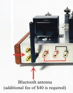
I expect it flickers in time with the music..
Did the manufacturer think that none tube savvy buyers would be fooled into thinking it was the rectifier, I wonder?
Did the manufacturer think that none tube savvy buyers would be fooled into thinking it was the rectifier, I wonder?
@jcalvarez
Would you be willing to share the sim and models? I think that would be useful for me to learn tube amps too.
Would you be willing to share the sim and models? I think that would be useful for me to learn tube amps too.
@Rallyfinnen sure, please find attached the components. PM me if there are any issues.
The post below includes the spreadsheet I used to create transformer models, very useful.
https://www.diyaudio.com/community/...ut-transformer-in-ltspice.405448/post-7506771
The post below includes the spreadsheet I used to create transformer models, very useful.
https://www.diyaudio.com/community/...ut-transformer-in-ltspice.405448/post-7506771
Attachments
@jcalvarez
Thank you for the sim! Got it running 'as is' but then I tried to make it 'basic', so removed the directives and wanted to do a bode plot of output impedance as I do on transistor amps, so ac analysis, no input, and 1Vac fed to the output via 1ohm resistor, and I get weird results. Maybe the transformer model does not work 'in reverse'? Seems to act only like a large inductance when I look at the plot. Or maybe the amp section is now 'dead'. Green is Vout and blue is RL current.
EDIT: feeding it 0.5V in and loading with 1ohm also seems to give no output, and DC operating points are missing for most nodes, except V1 voltage,
Last edited:
One thing to remember is that you are injecting a signal in two directions: One to the output transformer, and another one to the negative feedback circuit. The NFB will fight the signal change at the output. If you remove R7 (zero NFB) you will see the output signal going closer to the value you are injecting.@jcalvarez
Thank you for the sim! Got it running 'as is' but then I tried to make it 'basic', so removed the directives and wanted to do a bode plot of output impedance as I do on transistor amps, so ac analysis, no input, and 1Vac fed to the output via 1ohm resistor, and I get weird results. Maybe the transformer model does not work 'in reverse'? Seems to act only like a large inductance when I look at the plot. Or maybe the amp section is now 'dead'. Green is Vout and blue is RL current.
EDIT: feeding it 0.5V in and loading with 1ohm also seems to give no output, and DC operating points are missing for most nodes, except V1 voltage,
Here is an AC plot. Vin set to zero, R7 removed, I did not touch any of the original scripts, just added an .ac directive:
PS: I think you always need to run a DC operating point or an Transient script before an AC Sweep to set the DC operating points.
Last edited:
@jcalvarez
Thank you for the comments. I get it that the feedback should fight it, and that is why feedback should bring down the output impedance? I will try to play around with it some more. If I just feed it a signal at the input and plot up to 1MHz I see a spike in the top end, but maybe the sim/models are not to be trusted when it comes to stability up there? This is all new to me with output transformers and stuff 🙂 Must be a lot of parasitic capacitances etc.
@snapper
What are the benefits of the mods in the schematic you posted in post #116? Stability, distortion..?
I received the kit yesterday, and it looked to be in order. No major damage except a small dent on top of the chassis, but I was able to knock that out pretty well. There was a lot of sharp edges on the inside of the chassis, so I did some grinding with the Dremel so I won't cut my hands later when I assemble it. I still have not unpacked and checked the valves, but they seemed to be well protected.
everything from Asian forums :
http://www.haodiy.net/m/view.php?aid=7023&pageno=2
a lot of work for the translator --->
http://www.haodiy.net/m/view.php?aid=7023&pageno=1
https://bbs.hifidiy.net/ (currently not available)
Yes, I've also got stuck with my skin on the sharp edges of the sheet metal 😱
If the Chinese would screw the heavy mains transformer into the inside of the housing
for transport there would be no damage during transport !
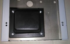

It is oscillating , maybe a simple mistake in wiring ...
And , as was said before , use equal resistors at phase splitter cathodyne , not 27K and 30K . This is a weird chinese "invention"
It turned out that the output transformers (P1/P2 each) had to be hooked up exactly in the opposite way as suggested by the label on said transformers.
With that change -- and it's been pointed out early on in this thread -- everything ended up working well, and the amp sounds good.
transformer (note label)
correct wiring
Not sure why the volume knob is "upside down" (clockwise -> softer) -- is this the design?
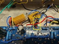
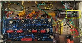
Just two LEDs that indicate that it's on.but what are the green components that I see in the photos?
I'm also adding a low voltage DC port on the back that I will use to drive some relays to automatically switch the speakers over to this amp when it's on. I can similarly use these relays to switch back and forth between two amps to seamlessly compare the sound.
Well, I think the heating filaments of the tubes are enough of an indication 😀LEDs that indicate that it's on.
now online again! There are many different tube amplifiers with 6F2 / 6P1 tubes 😎https://bbs.hifidiy.net/ (currently not available)
As far as I can see, the circuit is already 14 years old !
He designed the PCB so that you can choose 6P1 or EL84 / 6BQ5 / 6P14P using at solder jumper 😉
http://bbs.hifidiy.net/thread-309945-1-1.html
Last edited:
The little green LED thought so too, and exploded inside the case creating a short after a few hours of operation. Luckily the 25W input resistor took one for the team and protected the rest of the hardware.Well, I think the heating filaments of the tubes are enough of an indication 😀
Not sure what I was thinking hooking up a 120V AC LED assembly to a 250V DC source in 65C heat and thinking this was going to go well...
@davidswelt This 12v incandescent from eBay is what I used, connected to the heater supply.
They’re sold as dash indicators for custom cars.
Was not wanting a bright lamp, so a 12v running at 6v is perfect.
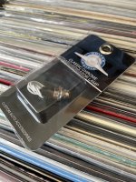
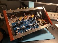
They’re sold as dash indicators for custom cars.
Was not wanting a bright lamp, so a 12v running at 6v is perfect.


Last edited:
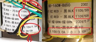
What still annoys me most about the delivery is that the mains transformer was not delivered with 230VAC as shown in the
sales pictures but with 220VAC and without the 6.3VAC 3A winding.😕
Does it really save so much copper costs or did the Chinese produce so much of the transformers in advance
and now want to get rid of them and have therefore reduced the price?
https://www.diyaudio.com/community/threads/problems-with-chinese-pp-kit.353111/page-5#post-7473748
The transformer is already pretty much maxed out in terms of heating output, there is about 19 watts of power missing.
What are your experiences? Does your transformer get very hot?
In any case, it is recommended to mount the transformer at a distance so that at least some air circulation can take place.
Unfortunately, there were no ventilation holes around the tubes. That it could also be better is the picture of another amplifier,
probably from the same manufacturer ! 😉
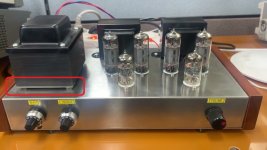
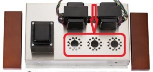


no idea what the Japanese did with this amplifier!? Looks wildly messed up, all components fitted on the other side of the board or omitted ?, different opts, additional choke and he writes something about GaN-FET GS-065-008 that is supposed to significantly improve the properties of the amplifier!
http://triesteaudio.blog.fc2.com/blog-entry-299.html
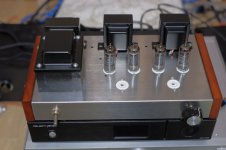
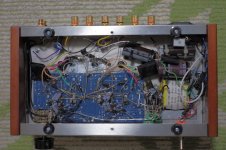
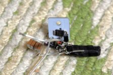
http://triesteaudio.blog.fc2.com/blog-entry-299.html


Last edited:
Not sure what he did , his skills are very bad ... but regulating the G2 of power tubes and 6F1 tube supply voltage is a good thing . This can change the sound .
- Home
- Amplifiers
- Tubes / Valves
- Problems with Chinese PP kit
